Methods and devices for rotating an active element and an energy emitter on a catheter

Inactive Publication Date: 2007-11-29
TYCO HEALTHCARE GRP LP
View PDF99 Cites 218 Cited by
  • Summary
  • Abstract
  • Description
  • Claims
  • Application Information

AI Technical Summary

Benefits of technology

[0011]In another aspect of the present invention, a catheter is provided which has a rotating active element and a rotating energy emitter. The active element is mounted to a shaft which has a lumen. The energy emitter is mounted to another shaft which extends through the lumen in the shaft of the active element. The energy emitting element and the active element may both be coupled to and driven by a single rotating driver. Although both rotating elements may be driven by the same driver, the elements may rotate

Problems solved by technology

Once in a sub-intimal space, it can be di

Method used


Image

  • Methods and devices for rotating an active element and an energy emitter on a catheter
  • Methods and devices for rotating an active element and an energy emitter on a catheter
  • Methods and devices for rotating an active element and an energy emitter on a catheter

Examples


Embodiment Construction

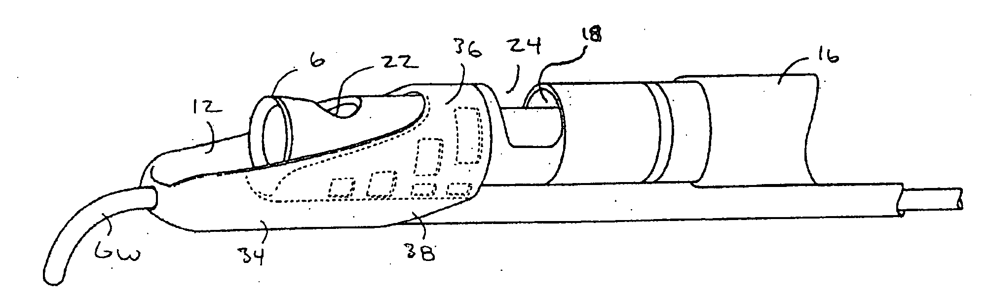
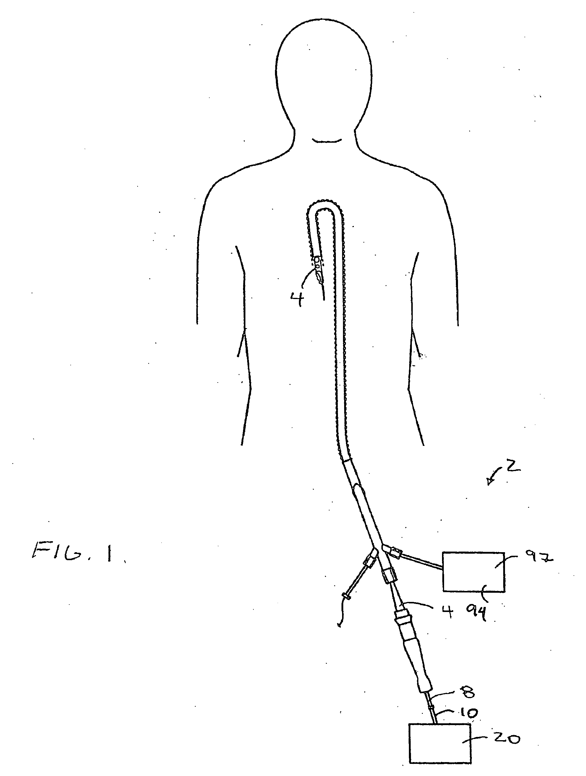
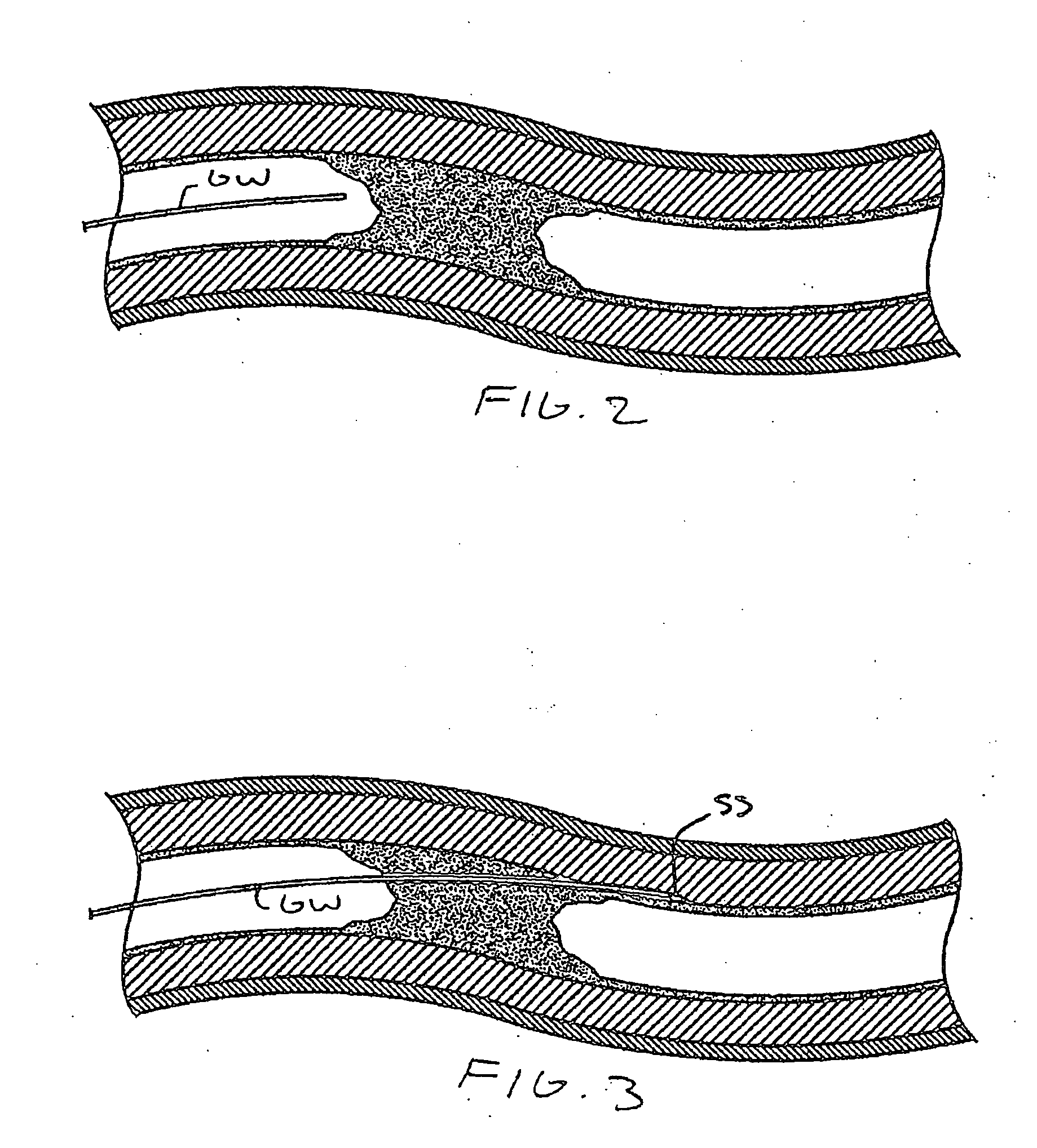
[0037]Referring to FIGS. 1-8, a system 2 and device 4 for reentering a true lumen from a subintimal space, dissection plane or so-called false lumen is shown. The device 4 includes a cutting element 6 coupled to a torque transmitting element 8, such as a wire 10, which rotates the cutting element 6. The device 4 has an opening 12 at a distal end 14 with the cutting element 6 movable between a stored position (FIG. 6) and a cutting position (FIGS. 7 and 8) which exposes the cutting element 6. The cutting element 6 may be any suitable cutting element 6 such as the cutting element 6 described in patents incorporated by reference above. The cutting element 6 has a circular cutting edge which has a diameter of about I mm although any suitable size may be used depending upon the particular application. The cutting element 6 may also be any other type of cutter such as a laser, ultrasound, RF or other type of cutter without departing from various aspects of the present invention.

[0038]The ...


PUM


Abstract

A tissue cutting device includes a sizing element which detects the diameter of the vessel in which the cutting device is positioned. The sizing element is coupled to the cutting element so that the amount of the cutting element that is exposed varies in response to movement of the sizing element.

Description

CROSS-REFERENCES TO RELATED APPLICATIONS[0001]This application is a continuation in part of U.S. patent application Ser. No. ______ entitled Methods and Devices for Cutting Tissue at a Vascular Location, filed ______ by Mike Rosenthal (Atty Docket No. 018489-002543US) which is hereby incorporated by reference.BACKGROUND OF THE INVENTION[0002]The present invention is directed to devices and methods for cutting tissue. In a specific application, the present invention is directed to devices and methods for re-entering the true lumen from a subintimal space such as a dissection plane or so-called “false lumen.”[0003]Guidewires and other interventional devices are used to treat vessels and organs using endovascular approaches. A guidewire is typically guided through blood vessels to the treatment site and the device is then advanced over the guidewire. For example, angioplasty and stenting are generally accomplished by first introducing a guidewire to the desired site and then advancing ...

Claims


Application Information

Patent Timeline
IPC IPC(8): A61B17/22A61B8/14
CPCA61B17/32002A61B17/320068A61B17/320758A61B17/320783A61B2017/22039A61B2019/528A61B2017/2905A61B2017/2927A61B2017/32004A61B2019/4857A61B2017/22095A61B2090/3784A61B2090/0811A61B2017/320069
Inventor ROSENTHAL, MIKE
Owner TYCO HEALTHCARE GRP LP
Why Eureka
Try Eureka