
High-radiation-efficiency circularly polarized antenna unit suitable for millimeter wave frequency band

A technology of circularly polarized antennas and millimeter wave frequency bands, applied in the structural form of radiating elements, the end feed of slender active units, antennas, etc., can solve the problem of large radiation loss and dielectric loss, constraints, and poor antenna radiation efficiency Advanced problems, to achieve the effect of improving the antenna impedance bandwidth, reducing the overall size, and reducing coupling energy

Pending Publication Date: 2022-04-15
NO 54 INST OF CHINA ELECTRONICS SCI & TECH GRP
View PDF0 Cites 1 Cited by
  • Summary
  • Abstract
  • Description
  • Claims
  • Application Information

AI Technical Summary

Problems solved by technology

[0003] The dipole / monopole antenna unit has the characteristics of wide bandwidth, high radiation efficiency, and high cross-polarization ratio. It is widely used in the design of base station antennas in the L / C band, but the dipole in the machining mode is mainly used. The sub / monopole antenna unit has limited processing technology in the millimeter wave frequency band, especially the coaxial-like feed structure is difficult to achieve equivalently, and its application in the millimeter wave frequency band is restricted
[0004] At present, the antenna form widely used in the millimeter wave frequency band is the multi-layer laminated microstrip patch antenna. In view of the high Q value of the microstrip antenna, large radiation loss and dielectric loss are generated when working in the high frequency band. The antenna's Radiation efficiency is not high (radiation efficiency is around 80%)

Method used


Image

  • High-radiation-efficiency circularly polarized antenna unit suitable for millimeter wave frequency band
  • High-radiation-efficiency circularly polarized antenna unit suitable for millimeter wave frequency band
  • High-radiation-efficiency circularly polarized antenna unit suitable for millimeter wave frequency band

Examples


Embodiment Construction

[0029] Below, the present invention will be further described in conjunction with the accompanying drawings and specific embodiments.

[0030] In order to illustrate the technical solutions of the embodiments of the present invention more clearly, the accompanying drawings of the embodiments will be briefly introduced below. Obviously, the accompanying drawings in the following description are only some embodiments of the present invention, and those of ordinary skill in the art Generally speaking, other drawings can also be obtained based on these drawings on the premise of not paying creative work.

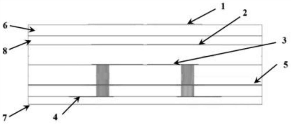
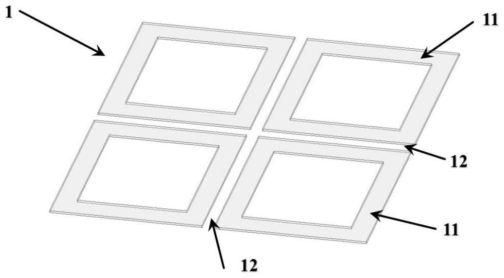
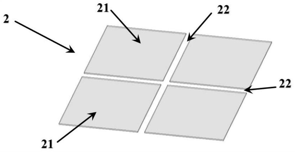
[0031] Such as Figure 1-Figure 4 As shown in , this embodiment is a new type of circularly polarized antenna unit with high radiation efficiency suitable for the millimeter wave frequency band. The antenna structure is a three-dimensional connection structure formed based on PCB processing technology, which is different from traditional mechanically processed antennas. The dif...


PUM


Abstract

The invention discloses a high-radiation-efficiency circularly polarized antenna unit suitable for a millimeter wave frequency band, and belongs to the technical field of antennas. The antenna is composed of four groups of monopole antennas which are distributed in a symmetrical structure, each group of monopole antennas comprises a feed structure, a main radiation sheet and a parasitic radiation sheet, and the four groups of monopole antennas feed excitation signals with equal amplitude and 90-degree phase difference in sequence according to the rotation direction to form a left-handed / right-handed circularly polarized antenna unit. The even / monopole type antenna unit is applied to the millimeter wave frequency band, can cover the frequency band width of 24.25-29.5 GHz, and has high radiation efficiency in the whole frequency band directional diagram.

Description

technical field [0001] The invention relates to the technical field of antennas, in particular to a circularly polarized antenna unit with high radiation efficiency suitable for millimeter wave frequency bands. Background technique [0002] Due to its abundant spectrum resources, millimeter-wave antennas have become the main evolution direction of the next generation of mobile communications (6G). At the same time, based on the millimeter-wave antenna system based on the AIP / AOB architecture, the antenna unit and the multi-channel radio frequency chip are interconnected in the vertical dimension, and the integration level has been significantly improved, which facilitates the construction of a larger-scale MIMO antenna. [0003] The dipole / monopole antenna unit has the characteristics of wide bandwidth, high radiation efficiency, and high cross-polarization ratio. It is widely used in the design of base station antennas in the L / C band, but the dipole in the machining mode i...

Claims


Application Information

Patent Timeline
IPC IPC(8): H01Q1/50H01Q1/38H01Q1/00H01Q1/52H01Q7/00H01Q9/30
Inventor 崔冠峰刘宁宋瑞良尚国涛
Owner NO 54 INST OF CHINA ELECTRONICS SCI & TECH GRP
Learn More