Coupled waveguide microstrip transition structure with low insertion loss

A technology of insertion loss and transition structure, which is applied in the direction of waveguide devices, antenna grounding switch structure connection, electrical components, etc., can solve the problems of limiting the increase of array antenna gain, radiation loss, and large size, so as to improve coupling energy and reduce Effect of radiant energy and low processing difficulty

Active Publication Date: 2022-04-05
UNIV OF ELECTRONICS SCI & TECH OF CHINA
View PDF4 Cites 0 Cited by
  • Summary
  • Abstract
  • Description
  • Claims
  • Application Information

AI Technical Summary

Problems solved by technology

[0002] With the rapid development of wireless communication technology and demand, antennas, as the key components that determine the performance of wireless systems, play a pivotal role; array antennas are in great demand in some long-distance communication scenarios due to their own high-gain characteristics; but in In some large antenna arrays, the loss on the feed transmission line cannot be underestimated, which greatly limits the improvement of the gain of the array antenna; therefore, the use of a transmission structure with lower loss has become an extremely effective way to improve the radiation efficiency and gain of the array antenna. method
[0003] For the feeding network of the array, there are usually unavoidable problems in the single-form feeding structure; although the waveguide transmission line has extremely low transmission loss, due to the limitation of the transmission mode, its own size is large; and for the microstrip For transmission lines, although they have smaller size and more flexible wiring, as the array size increases, the increase in line length will bring non-negligible losses
In order to have a compact structure and low insertion loss, a hybrid network of waveguide and microstrip line is often used in engineering to realize large-scale array feeding; this type of structure is a multi-layer structure, and the waveguide and microstrip are located on different layers. , energy is coupled from the waveguide to the microstrip line through a transition structure; however, since the microstrip line is an open transmission line, in the process of energy coupling from the waveguide to the microstrip line, there is inevitably a part of the energy coupled into the space , resulting in a certain radiation loss; therefore, how to reduce the radiation loss of the transition structure as much as possible while ensuring the integrity of the structural function has become a research focus of great significance and value.

Method used


Image

  • Coupled waveguide microstrip transition structure with low insertion loss
  • Coupled waveguide microstrip transition structure with low insertion loss
  • Coupled waveguide microstrip transition structure with low insertion loss

Examples


Embodiment Construction

[0016] The present invention will be described in further detail below in conjunction with the embodiments and accompanying drawings.

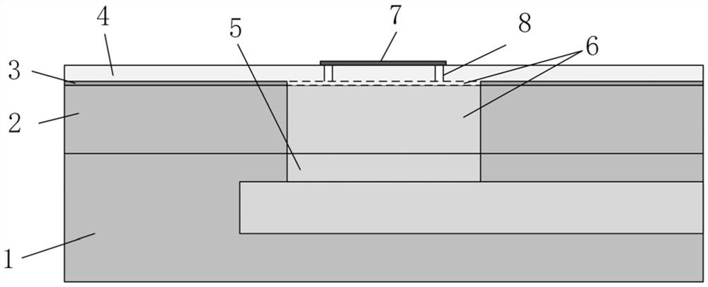
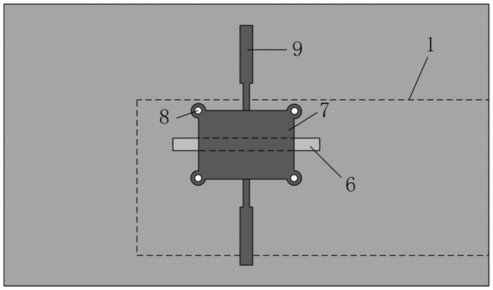
[0017] This embodiment provides a coupled waveguide microstrip transition structure with low insertion loss, the structure of which is as follows figure 1 , figure 2 As shown, it specifically includes: a lower rectangular metal waveguide 1, an intermediate transition layer 2, a ground metal plate 3, and an upper dielectric plate 4 that are stacked sequentially from bottom to top, wherein the upper surface of the lower rectangular metal waveguide 1 is provided with a rectangular coupling slot. 5. The intermediate transition layer 2 and the ground metal layer 3 are provided with coupling grooves 6 of the same size corresponding to the positions of the rectangular coupling slits 5. The upper surface of the upper dielectric board 4 is provided with a rectangular metal patch 7, and the centerline of the rectangular metal patch It is set coinciden...


PUM

PropertyMeasurementUnit
thicknessaaaaaaaaaa
thicknessaaaaaaaaaa
thicknessaaaaaaaaaa

Abstract

The invention belongs to the technical field of microwave transmission lines, and particularly provides a coupling type waveguide microstrip transition structure with low insertion loss, which is used for meeting the requirement of the transition structure for reducing radiation loss. The antenna comprises a lower-layer rectangular metal waveguide 1, a middle transition layer 2, a grounding metal plate 3, an upper-layer dielectric plate 4 and a rectangular metal patch which are sequentially stacked from bottom to top, and the rectangular metal patch is introduced to the upper surface of the upper-layer dielectric plate, so that the coupling energy is greatly improved, and meanwhile, the radiation energy is remarkably reduced; therefore, the transmission coefficient from the waveguide to the microstrip line is obviously improved, and a good port reflection characteristic is also maintained; meanwhile, the short-circuit probe is ingeniously applied, the influence of impedance mismatch caused by the short-circuit probe is counteracted while the rectangular metal patch effect is achieved, and impedance matching is achieved; moreover, compared with the prior art, the structure is simple, the processing difficulty is low, and industrial production is easy to realize.

Description

technical field [0001] The invention belongs to the technical field of microwave transmission lines, relates to a transition structure converted from a waveguide transmission line to a microstrip transmission line, and specifically provides a coupled waveguide microstrip transition structure with low insertion loss. Background technique [0002] With the rapid development of wireless communication technology and demand, antennas, as the key components that determine the performance of wireless systems, play a pivotal role; array antennas are in great demand in some long-distance communication scenarios due to their own high-gain characteristics; but in In some large antenna arrays, the loss on the feed transmission line cannot be underestimated, which greatly limits the improvement of the gain of the array antenna; therefore, the use of a transmission structure with lower loss has become an extremely effective way to improve the radiation efficiency and gain of the array ante...

Claims


Application Information

Patent Timeline
Patent Type & Authority Applications(China)
IPC IPC(8): H01P5/107H01Q21/00H01Q1/50
CPCY02D30/70
Inventor 王博宁杨德强赵志钦孙凯陶婷婷刘思豪
Owner UNIV OF ELECTRONICS SCI & TECH OF CHINA
Why Eureka
Try Eureka