Delivery catheter having active engagement mechanism for prosthesis

a technology of prothesis and delivery catheter, which is applied in the field of interventional catheters and prostheses, can solve the problems of stents, stents, and vascular disease, and achieve the effect of convenient accurate control of working or deployed length

Active Publication Date: 2007-11-29
JW MEDICAL SYSTEMS LTD
View PDF6 Cites 133 Cited by
  • Summary
  • Abstract
  • Description
  • Claims
  • Application Information

AI Technical Summary

Benefits of technology

[0014] The present invention provides devices and methods for delivering prostheses, particularly stents, into body lumens. In several preferred embodiments, the devices and methods facilitate accurate control of the working or deployed length of a multi-segment stent or other prosthesis by providing valve members that effectively and consistently separate a first prosthesis segment or plurality of prosthesis segments from a second prosthesis segment or plurality of prosthesis segments carried by the delivery device. Preferably, the valve members function actively, by selectively moving between a contracted configuration in which the valve member allows movement of prostheses out of an outer sheath, and an extended configuration in which the valve member inhibits movement of prostheses out of the sheath.

Problems solved by technology

This blocks blood flow to the heart muscle, potentially causing myocardial infarction.
In some cases, however, balloon angioplasty alone is inadequate to treat vascular disease due to restenosis, the renarrowing of the artery following angioplasty.
Stents, however, have also suffered from the problem of restenosis.
However, it is believed that restenosis may be caused in some cases by the excessive stiffness of current stents and their inability to conform to vascular curves, shapes, dimensional changes, and movements.
This problem is particularly acute with longer lesions, which may extend over curved and tapered sections of a vessel and may be subject to non-uniform movements along their lengths.

Method used


Image

  • Delivery catheter having active engagement mechanism for prosthesis
  • Delivery catheter having active engagement mechanism for prosthesis
  • Delivery catheter having active engagement mechanism for prosthesis

Examples


first embodiment

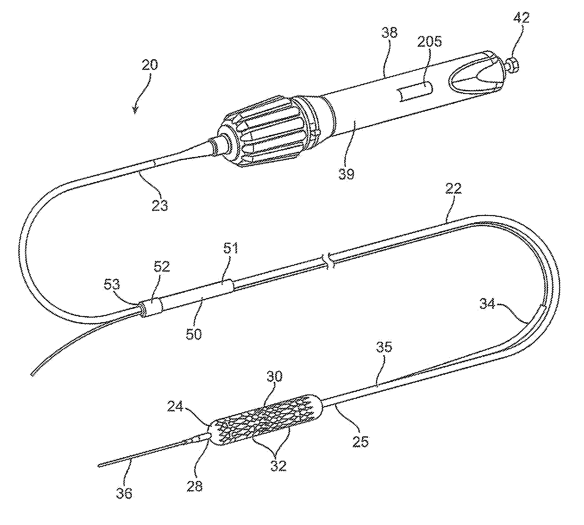
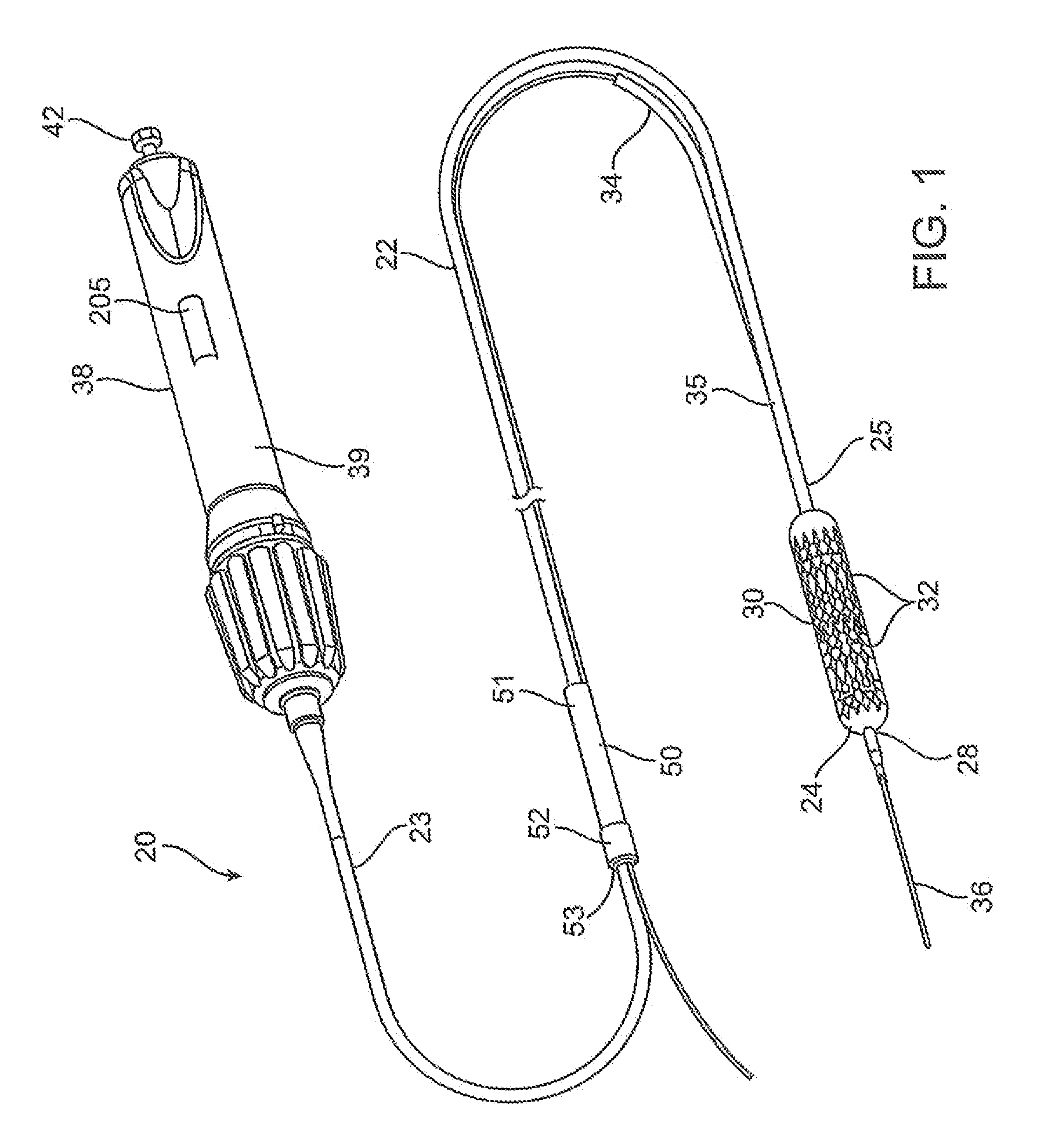
[0092] a stent delivery catheter according to present invention is illustrated in FIG. 1. The stent delivery catheter 20 includes a catheter body 22 comprising an outer sheath 25 slidably disposed over an inner shaft 27 (not shown in FIG. 1). An expandable member 24, preferably an inflatable balloon (shown in an inflated configuration), is mounted to the inner shaft 27 and is exposed by retracting the sheath 25 relative to the inner shaft 27. A tapered nosecone 28, composed of a soft elastomeric material to reduce trauma to the vessel during advancement of the device, is mounted distally of expandable member 24. A stent 30, which preferably comprises a plurality of separate or separable stent segments 32, is disposed on the expandable member 24 for expansion therewith. A guidewire tube 34 is slidably positioned through a guidewire tube exit port 35 in the sheath 25 proximal to the expandable member 24. A guidewire 36 is positioned slidably through the guidewire tube 34, the expandab...

second embodiment

[0222] In the second embodiment, illustrated in FIG. 31B, a rigid retainer 350 surrounds an elastomeric member 352. The retainer is generally cylindrical, and is provided with a conical inner surface 351. The conical inner surface 351 terminates at the distal end of the retainer where a gap “h” is provided. The gap “h” is preferably of a size large enough to allow passage of the stent segment(s) 32 with adequate clearance to prevent hang-ups or inadvertent engagements. The elastomeric member 352 has a relatively short cylindrical shape, and is in contact with the inner surface of the retainer 350. A generally cylindrical expansion element 354 is adjacent to the elastomeric member 352. As shown in FIG. 31B, a portion of the expansion element 354 may extend outside of the retainer 350. Alternatively, the expansion element 354 may be fully contained within the retainer 350. In either case, the expansion element 354 is fixed in position relative to the retainer 350, as both components a...


PUM


Abstract

Delivery catheters and systems are adapted for delivering multiple discreet prostheses in body lumens. An exemplary delivery catheter comprises a sheath, a pusher for moving the prostheses relative to the sheath, and a valve member for selectively retaining the prostheses in the sheath. For balloon expandable stents, an elongated shaft and an expandable member are slidably disposed in the sheath, and the prostheses are positionable on the expandable member for deployment in the body lumen. The valve member allows a selected number of prostheses to be deployed from the sheath while retaining other prostheses within the sheath.

Description

CROSS-REFERENCE TO RELATED APPLICATIONS [0001] The present application claims the benefit of priority to U.S. Provisional Patent Application Ser. No. 60 / 747,774 filed May 19, 2006, and is also a continuation-in-part of co-pending U.S. patent application Ser. No. 11 / 538,904 filed Oct. 5, 2006, which is a divisional of U.S. patent application Ser. No. 10 / 412,714 filed Apr. 10, 2003, which is a continuation-in-part of U.S. patent application Ser. No. 10 / 306,813 filed Nov. 27, 2002, which is a non-provisional of U.S. Provisional Patent Application Ser. No. 60 / 336,967 filed Dec. 3, 2001, and is also a non-provisional of U.S. Provisional Patent Application Ser. No. 60 / 364,389 filed Mar. 13, 2002, each of which is hereby incorporated by reference in its entirety.BACKGROUND OF THE INVENTION [0002] The present invention relates generally to interventional catheters and prostheses, and more specifically to catheters and prostheses for treatment of vascular diseases, including coronary artery ...

Claims


Application Information

Patent Timeline
Patent Type & Authority Applications(United States)
IPC IPC(8): A61F2/06A61F2/82
CPCA61F2/958A61F2/962A61F2/966A61F2250/0071A61F2002/9511A61F2002/9583A61F2002/826
Inventor ANDREAS, BERNARD H.MCDONALD, MATTHEWDAULTON, JAY S.LEOPOLD, ANDREWLEOPOLD, PHILIPMAULDING, MATTBLACK, ANDREW
Owner JW MEDICAL SYSTEMS LTD
Why Eureka
Try Eureka