
Method In A Safety System For Controlling A Process Or Equipment

a safety system and control system technology, applied in the direction of safety arrangments, testing/monitoring control systems, instruments, etc., can solve the problems of different safety events, complex combination of system and components, plant shut down, etc., to reduce the chance of human error in design, improve safety system reliability, and cost-effective

Inactive Publication Date: 2007-11-29
ABB RES LTD
View PDF14 Cites 32 Cited by
  • Summary
  • Abstract
  • Description
  • Claims
  • Application Information

AI Technical Summary

Benefits of technology

[0008] The major advantage of the invention is that an auto-generation of the Human machine interface (HMI) in parallel with auto-generation of control code makes safety systems more reliable since it reduces the chance of introducing human error in design.
[0009] Another advantage of the invention is that the resulting complete safety system can be more fully tested earlier in the product development cycle.
[0010] Yet another advantage of the invention is that the resulting complete safety system is created in a more cost-effective, work-effective and timesaving manner.
[0011] Safety engineering tools that can generate control system software automatically offer better quality for this reason and are also inherently verified.
[0012] The system may be implemented as a server function, wherein the safety system is created and recreated thousands of times on hundreds of objects.
[0013] In another aspect of the invention, a method is described for an auto-generation of the HMI (Human machine interface) dependent on auto-generation of control code. The method includes use of the human-machine interface of the invention comprising information displayed by the visual display and use of the display, and generation means to generate the operator display.

Problems solved by technology

This results in a complex combination of system and components.
As part of the functions of the elements in the system, measurements on parameters such as currents, voltages, phases, temperatures and so on are made substantially continuously and may result in different safety events, including even a plant shut-down.
Current engineering toolsets do not have a safety emphasis as a first priority.
However, secure safety control code is compromised if there is a bug in the hand-coded function, such as an operator display, which gives a wrong indication.

Method used


Image

  • Method In A Safety System For Controlling A Process Or Equipment
  • Method In A Safety System For Controlling A Process Or Equipment
  • Method In A Safety System For Controlling A Process Or Equipment

Examples


Embodiment Construction

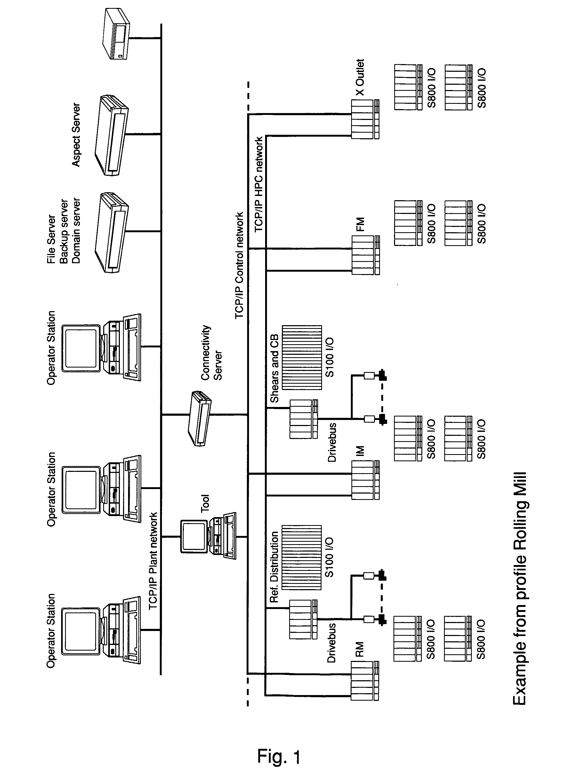
[0043]FIG. 1 shows elements of an industrial control system in a simplified block diagram. The safety system is comprised in the control system or functions as an individual system in parallel with the control system, sometimes even enabling the same action, but with different decision chains.

[0044] The construction of the safety system structure is not unlike a tic-tac-toe game. Every object has a predefined relation to all other objects. The method involves auto-generating a Human machine interface (HMI) in parallel with autogeneration of a control code. The safety system generates atomically the graphical object for the operator displays, which exposes the entire underlying object's functionality, such as access to data, start / stop or another functions. These graphical objects are automatically arranged on the display to reflect the arrangement in the safety program.

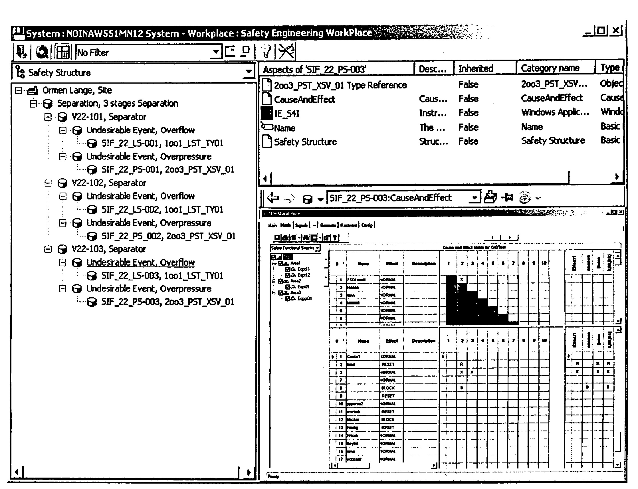
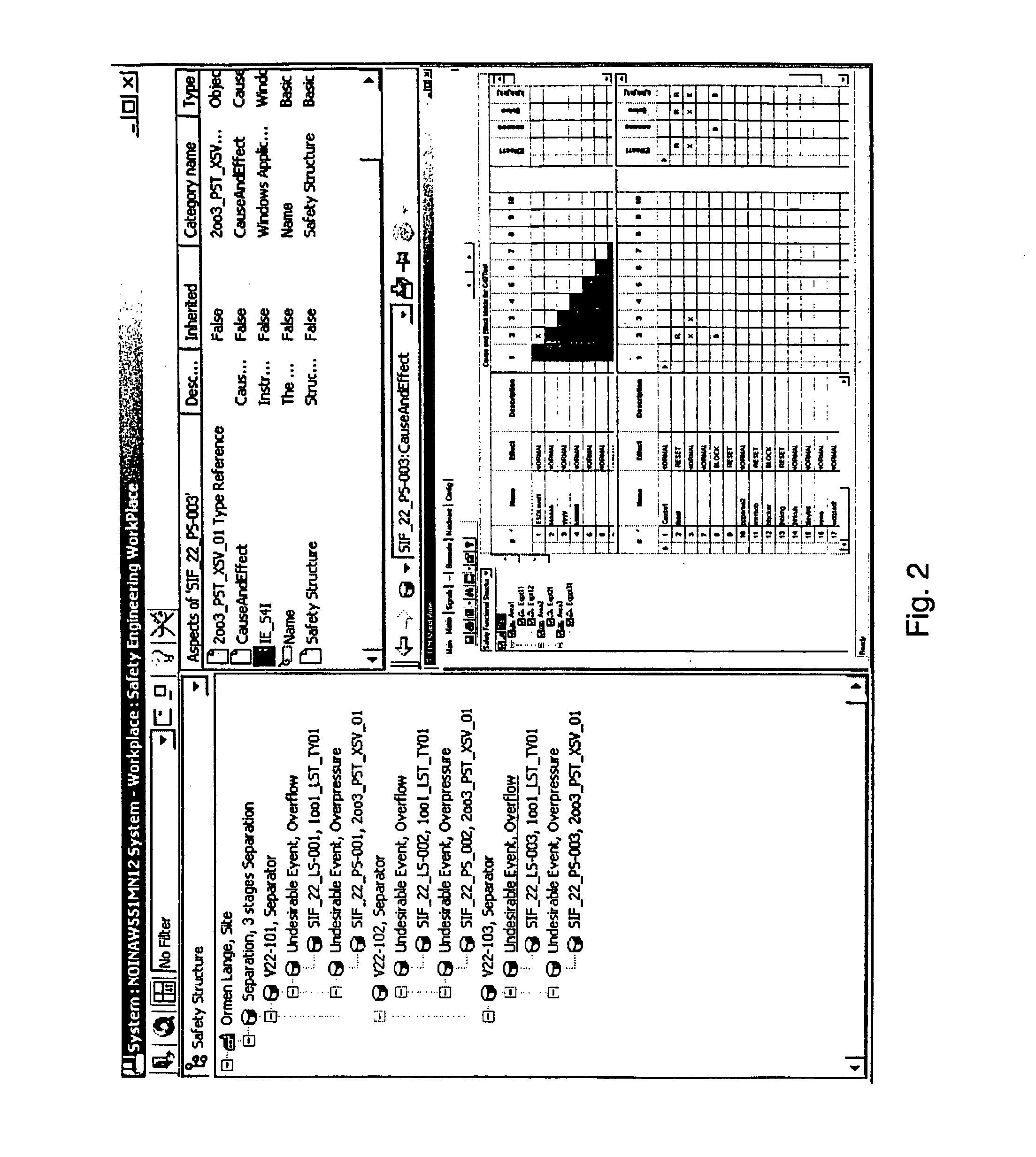
[0045]FIG. 2 shows a preferred embodiment of a safety display. The display is associated with selection means for...


PUM


Abstract

A method in an industrial safety system for controlling a process or equipment. The industrial safety system including components with safety devices. The safety system enables signals to be generated as a result of an event or alarm. An automated link is created between the event or alarm and an action to be taken upon receipt of the event or alarm signal due to the event. A control signal is generated to initiate the action. Also, a computerized system according to the method.

Description

TECHNICAL FIELD [0001] A method in an industrial safety system for controlling a process or equipment, which industrial safety system comprises components with inputs and safety devices, that enables signals to be generated as a result of an event or alarm, wherein an event or alarm causes a signal to be generated. A method for handling events in an industrial system, such as alarms. A method for enabling an action according to an event in an industrial system, such as an alarm or other events. BACKGROUND ART [0002] An industrial process has a physical implementation comprising components such as devices and apparatuses for operation, control, regulation and protection of the process. The industrial process also comprises systems for functionality, control and supervision. This results in a complex combination of system and components. In such an industrial process it is necessary to protect the process or an environment individual, systems subsystems and / or components. As part of t...

Claims


Application Information

Patent Timeline
Patent Type & Authority Applications(United States)
IPC IPC(8): G05B9/02G05B23/02
CPCG05B23/027G05B9/02
Inventor MARTINEZ, ROBERTJUEL, PERFJELLDALEN, PER
Owner ABB RES LTD
Learn More