
Heat exchange tube and evaporator

Inactive Publication Date: 2007-12-06
SHOWA DENKO KK
View PDF13 Cites 20 Cited by
  • Summary
  • Abstract
  • Description
  • Claims
  • Application Information

AI Technical Summary

Benefits of technology

[0007]An object of the present invention is to solve the above problem and to provide a heat exchange tube which, when used in an evaporator, enables a reduction in the temperature difference between air discharged into the compartment of an automobile when a compressor is turned ON and that when the compressor is turned OFF, as well as an evaporator.
[0008]While conducting various studies, the inventors of the present invention have focused on heat exchange tubes and found that the temperature difference between air discharged into the compartment of an automobile when a compressor is turned ON and that when the compressor is turned OFF can be reduced through improvement of retainability of liquid within channels of heat exchange tubes used in an evaporator. Specifically, we have found the following: even after the compressor is turned OFF, while a liquid-phase refrigerant remains in the channels of heat exchange tubes of the evaporator, heat exchange continues between the remaining liquid-phase refrigerant and air which passes through the evaporator, so that an abrupt increase in discharge air temperature can be restrained.

Problems solved by technology

This may have adverse effect on the fuel economy of an automobile.

Method used


Image

  • Heat exchange tube and evaporator
  • Heat exchange tube and evaporator
  • Heat exchange tube and evaporator

Examples


example 1

[0102]The evaporator 20 was prepared which employed the heat exchange tubes 34 each having the configuration shown in FIG. 4; i.e., the number of the refrigerant channels 34a is 11, and the number of the protrusions 346 on the inner peripheral surface of each of the refrigerant channels 34a excluding the opposite-end refrigerant channels 34a is 4.

example 2

[0103]An evaporator was prepared which employed heat exchange tubes 34A each having the configuration shown in FIG. 13a; i.e., the number of the refrigerant channels 34a is 14, and the number of the protrusions 346 on the inner peripheral surface of each of the refrigerant channels 34a excluding the opposite-end refrigerant channels 34a is 4.

example 3

[0104]An evaporator was prepared which employed heat exchange tubes 34B each having the configuration shown in FIG. 13b; i.e., the number of the refrigerant channels 34a is 16, and the number of the protrusions 346 on the inner peripheral surface of each of the refrigerant channels 34a excluding the opposite-end refrigerant channels 34a is 4.


PUM


Abstract

An evaporator includes a plurality of flat heat exchange tubes extending in a vertical direction and arranged at intervals along a left-right direction with a width direction thereof coinciding with a front-rear direction. The heat exchange tube has a plurality of refrigerant channels arranged along the width direction. The evaporator satisfies a relation 0.558≦A≦1.235, where A is a value in pieces / mm obtained by dividing the number N of the refrigerant channels of the heat exchange tube by a width W of the heat exchange tube as measured in the front-rear direction. Also, the evaporator satisfies a relation 0.35≦Dh≦1.0, where Dh is an equivalent diameter in mm of the heat exchange tube. This evaporator can reduce the temperature difference between air discharged into a compartment when a compressor is turned ON and that when the compressor is turned OFF.

Description

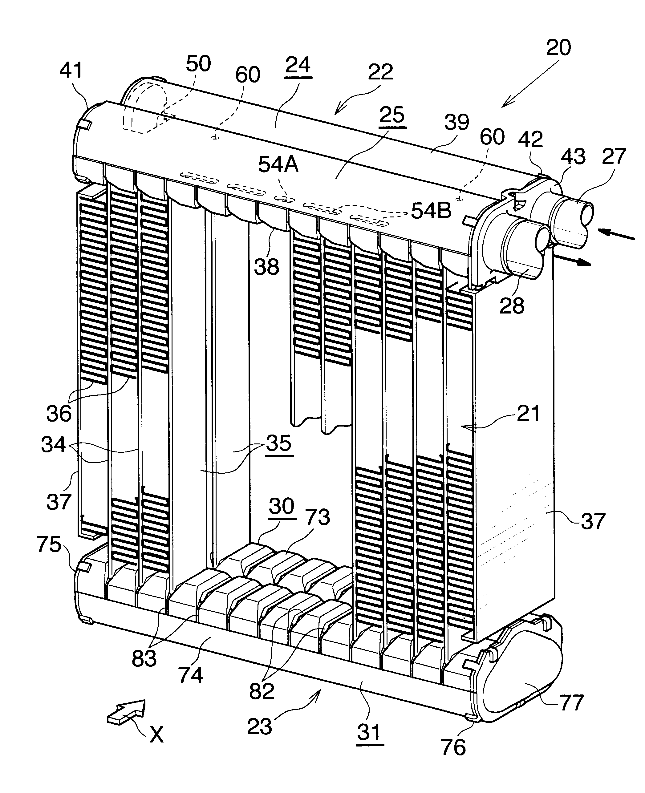
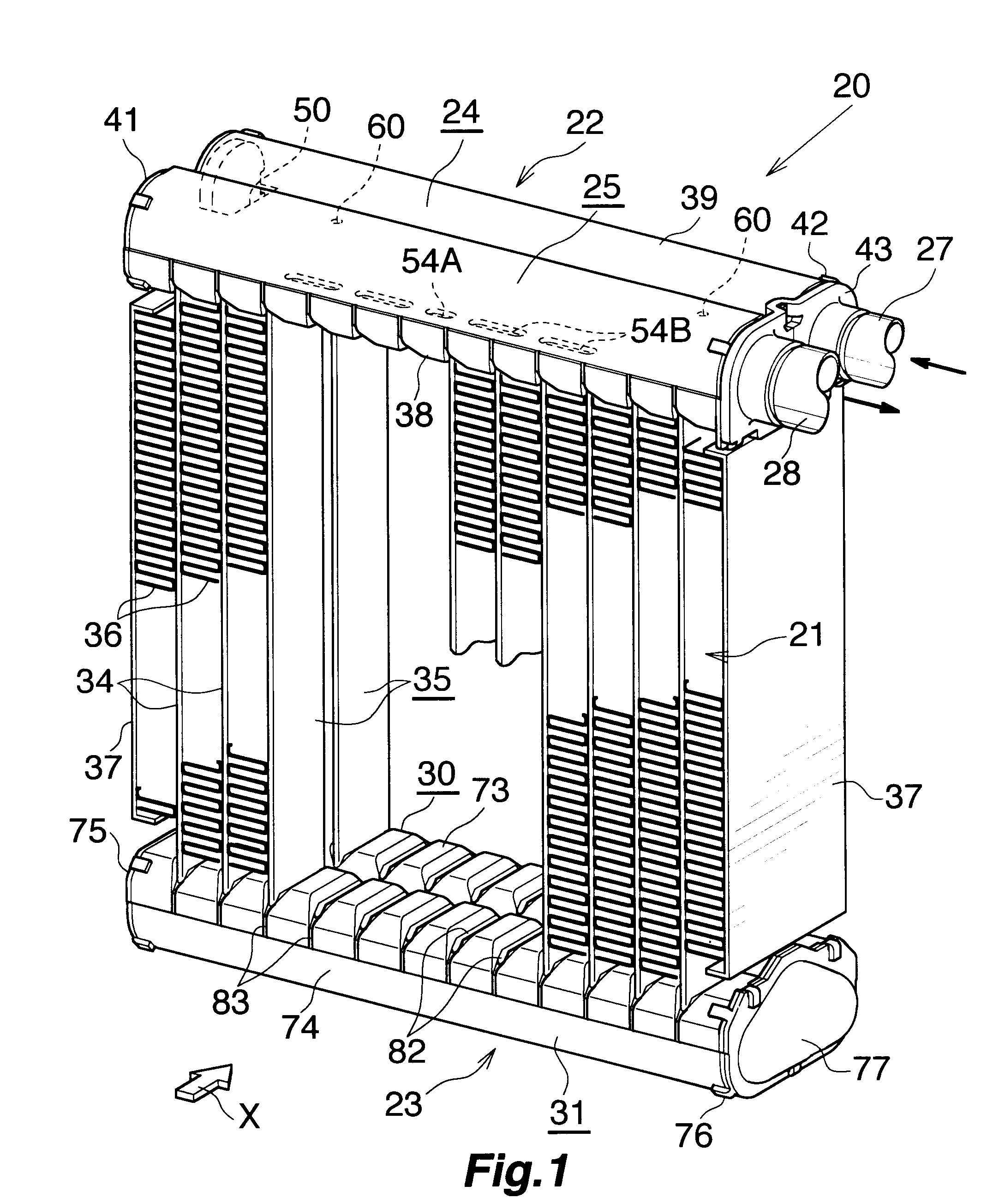
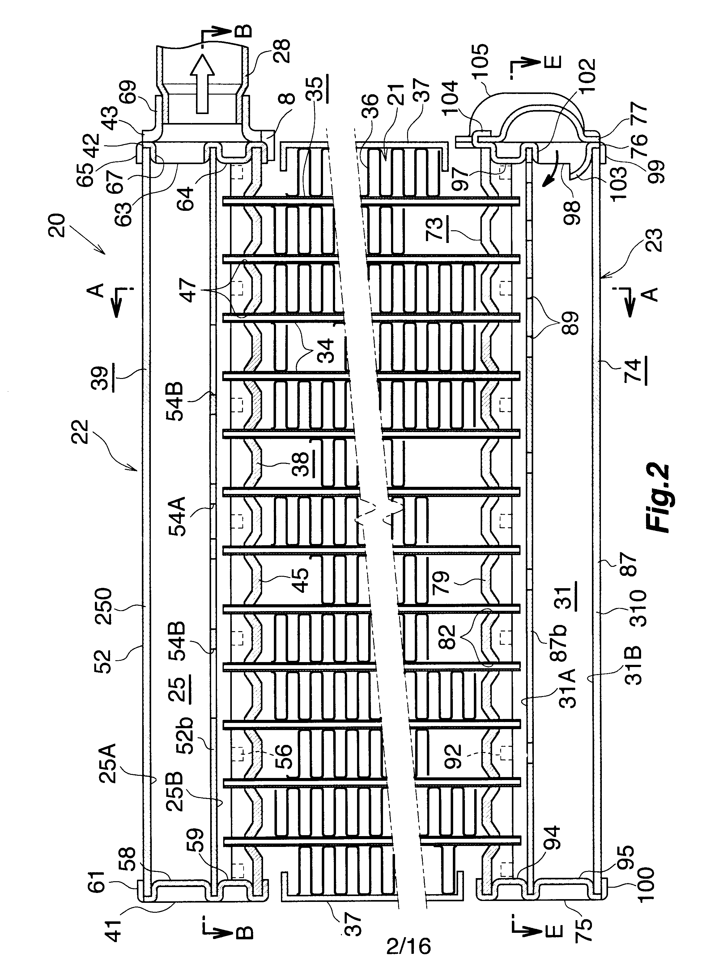
BACKGROUND OF THE INVENTION[0001]The present invention relates to a heat exchange tube and an evaporator, and more particularly to a heat exchange tube preferably used in, for example, an evaporator of a car air conditioner, which is a refrigeration cycle to be mounted on an automobile, as well as to an evaporator.[0002]Herein and in the appended claims, the downstream side (a direction represented by arrow X in FIG. 1) of an air flow through air-passing clearances between adjacent heat exchange tubes will be referred to as the “front,” and the opposite side as the “rear,” and the upper, lower, left-hand, and right-hand sides of FIG. 2 will be referred to as “upper,”“lower,”“left,” and “right,” respectively. Also, herein, the term “aluminum” encompasses aluminum alloys in addition to pure aluminum.[0003]Conventionally, a so-called laminated evaporator has been widely employed as an evaporator for use in a car air conditioner. In the laminated evaporator, a plurality of flat, hollow ...

Claims


Application Information

Patent Timeline
IPC IPC(8): F28D1/02F28D7/06F25B39/02
CPCF25B39/022F25B2500/01F28D1/05391F28D2021/0085F28F1/022F28F2220/00F28F1/40F28F3/048F28F9/0204F28F9/0246F28F1/126
Inventor HIGASHIYAMA, NAOHISAMORI, DAISUKEWATANABE, SUMITAKA
Owner SHOWA DENKO KK
Learn More