Electrical conductive contact ring for electroplating or electrodeposition

a contact ring and electrodeposition technology, applied in the field of electroplating or electrodeposition, can solve the problems of inconsistent metal coating on the surface, difficulty in creating a continuous electrical contact with moving endless tubes, and known methods of brush-to-tube conductive contact tend to be somewhat intermittent, so as to achieve a long life and minimal service

Inactive Publication Date: 2007-12-06
ILLINOIS TOOL WORKS INC
View PDF54 Cites 19 Cited by
  • Summary
  • Abstract
  • Description
  • Claims
  • Application Information

AI Technical Summary

Benefits of technology

[0010]An advantage of the present invention is providing a contact ring useful for coating processes for plating continuous cylindrical objects moving through the contact ring.
[0011]Another advantage of the present invention is providing an electrical contact ring for an electro-coating process that is of long life useful and requires minimal service.
[0012]Still another advantage of the present invention is providing an annular contact ring for cylindrical objects or other similar shapes to be electro-coated that can be provided in different sizes for plating objects of different diameters.
[0013]Yet another advantage of the present invention is providing an electrical contact system for moving cylindrical objects that provides substantially consistent electrical contact around the circumference of the object.
[0014]Other features and advantages of the invention will become apparent to those skilled in the art upon review of the following detailed description, claims and drawings in which like numerals are used to designate like features.

Problems solved by technology

Creating a continuous electrical contact with a moving endless tube has presented difficulties.
A problem known in the tube coating industry is that known methods of brush to tube conductive contact tend to be somewhat intermittent.
Intermittent electrical contact with the moving tube can cause inconsistent metal coating on the surface and possibly even extended areas of poor coating or voids that have no coating.
Known brush contacts for electroplating continuous tubing wear relatively quickly and require frequent replacement.

Method used


Image

  • Electrical conductive contact ring for electroplating or electrodeposition
  • Electrical conductive contact ring for electroplating or electrodeposition
  • Electrical conductive contact ring for electroplating or electrodeposition

Examples


Embodiment Construction

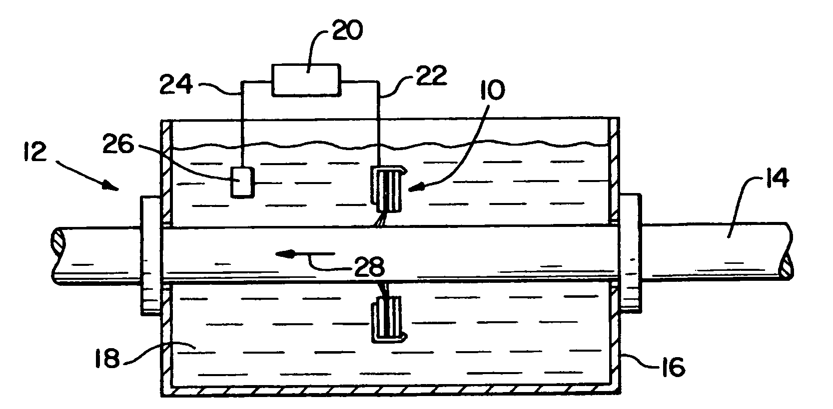
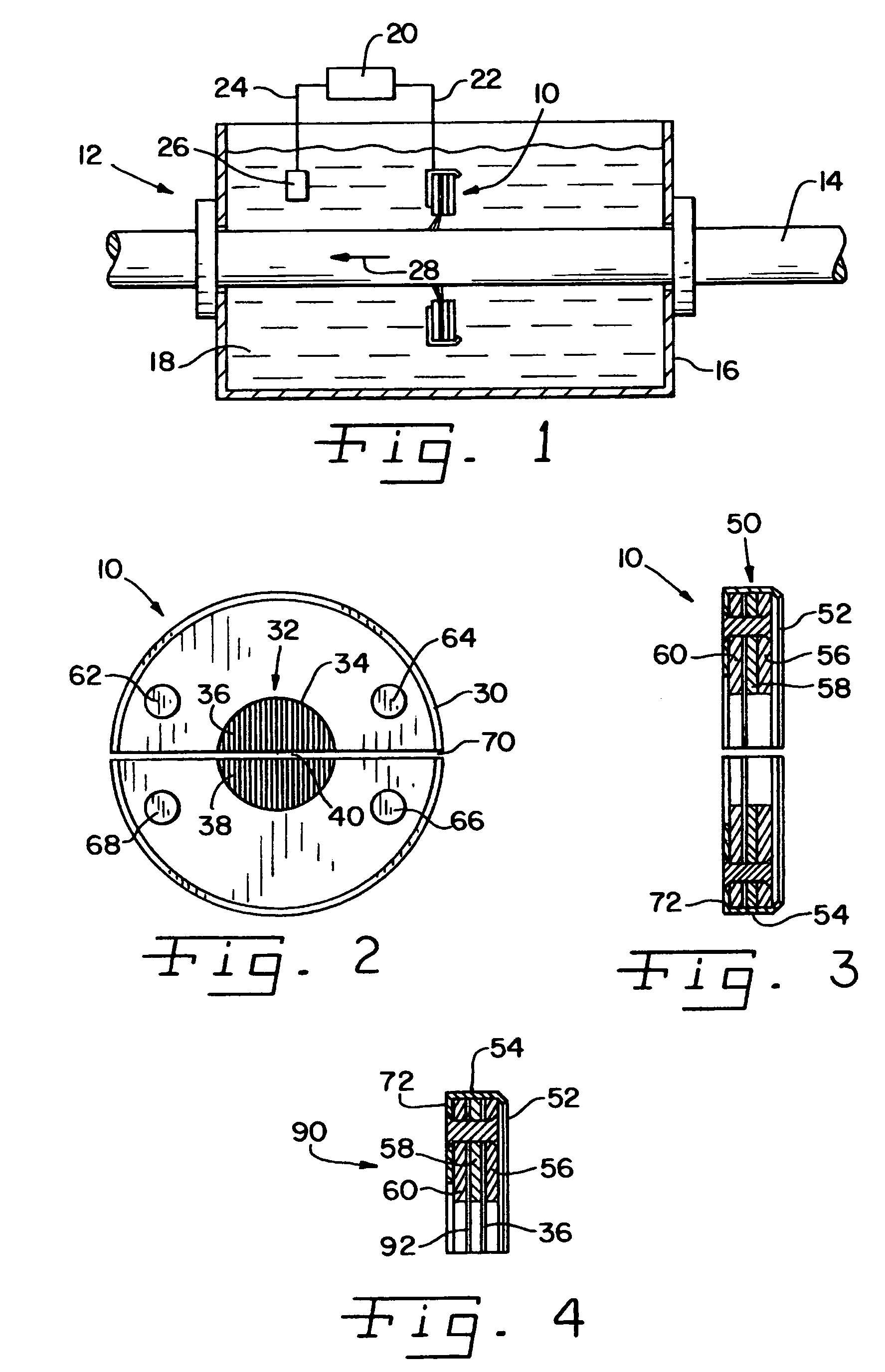
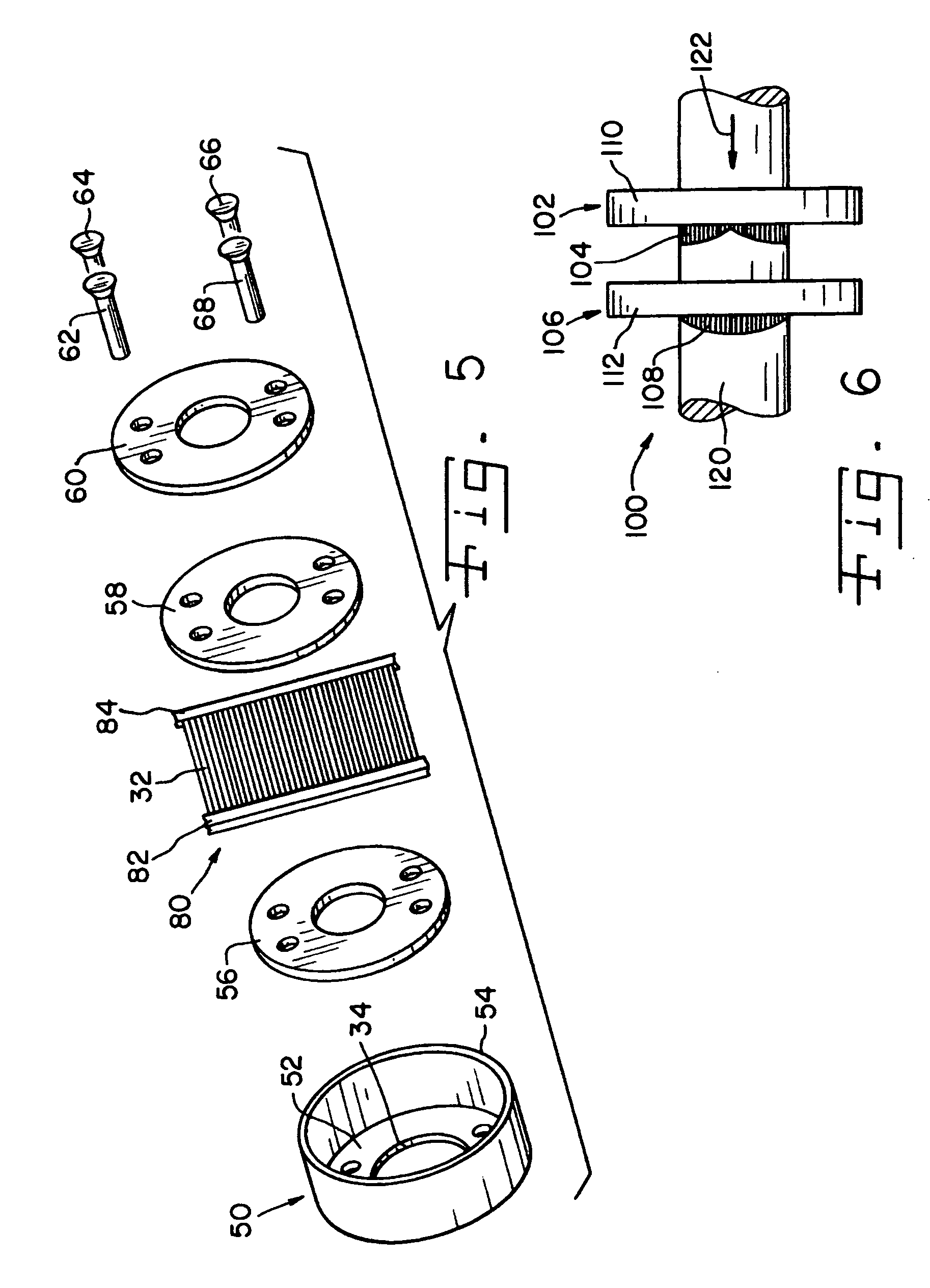
[0022]Referring now more specifically to the drawings and to FIG. 1 in particular, an electrical conductive contact ring 10 in accordance with the present invention is shown in a process assembly 12 for providing a coating on an endless length of tube 14. Process assembly 12 includes a bath 16 having a plating solution 18 therein, which may be a solution of a metallic ion such as, for example, silver, gold, copper, nickel and others. A DC power source 20 is electrically connected via the cathode pole thereof through a cathode connection 22 to contact ring 10 and via the anode pole thereof through an anode connection 24 to a sacrificial anode 26 that replenishes the metal ions in solution 18 that are deposited on tube 14.

[0023]Contact ring 10 of the present invention can be used for known electroplating or electrodeposition processes to establish a continuous connection between the cathode pole of DC power source 20 and a moving cylindrical or rod-like member, such as continuous tube...


PUM

PropertyMeasurementUnit
sizeaaaaaaaaaa
electrically conductiveaaaaaaaaaa
diameteraaaaaaaaaa

Abstract

A conductive contact ring for an electroplating or electrodeposition process on a cylindrical surface includes a frame defining an opening through which the object can be passed and an array of electrically conductive fibers spanning the opening. The frame is electrically conductive and is connected to a DC power source in the process. Two or more contact rings can be used in a process to provide consistent electrical contact with the surface sliding therethrough. A single contact ring can have first and second groups of filaments spaced from each other along the axial length of the surface.

Description

FIELD OF THE INVENTION[0001]The present invention relates generally to electro-coating processes, such as electroplating and electrodeposition processes, and, more particularly, the invention pertains to such processes for tubing and even more particularly to the electrical contact formed with the tubing in an electrodeposition or electroplating process.BACKGROUND OF THE INVENTION[0002]Electroplating and electrodeposition have been used to provide surface layers on parts of many types, including tubing used in manufacturing coaxial cables to shield the conductor in the cable from ambient signals that would adversely affect the performance of the cable. In a known tubular coating process a continuous tube is pulled through a bath solution with conductive metal ions therein, such as, for example, silver, gold, copper, nickel and others. A cathode (negative pole) connection of a DC power supply is made with the endless tube. An anode of the metal used in the coating process is connecte...

Claims


Application Information

Patent Timeline
Patent Type & Authority Applications(United States)
IPC IPC(8): C25B9/00C25D17/10
CPCC25D17/005C25D7/04
Inventor BARNARD, MICHAEL P.OH, HIEYOUNG W.RICHARDSON, JEFFREY W.
Owner ILLINOIS TOOL WORKS INC
Why Eureka
Try Eureka