Wetness monitoring system

a monitoring system and wetness technology, applied in the field of wetness monitoring system, can solve the problems of increasing difficulty, time-consuming and laborious, and prolonged sitting in wet or soiled diapers or garments, and achieve the effect of reducing the annual operating cost of the system, facilitating positioning, and reducing the operating cos

Inactive Publication Date: 2007-07-31
RF TECH
View PDF63 Cites 227 Cited by
  • Summary
  • Abstract
  • Description
  • Claims
  • Application Information

AI Technical Summary

Benefits of technology

[0020]A still further advantage of the present wetness monitoring system is that operating costs are reduced. The sensor is designed to be washed up to four times and used five times before disposal. The backing layer of the sensor is made of a durable, shrink and tear resistant material. The two spaced, conductive sensor strips are uniformly glued or otherwise secured throughout the entire top surface of the backing layer. Similarly, the absorbent layer is uniformly secured throughout the entire top surfaces of the backing layer and sensor strips. The selected materials and sensor design forms an integral sensor that maintains its shape and integrity for a limited number of uses and wash cycles. This reusability dramatically reduces the annual operating cost of the system. A person may only require a few hundred sensors on an annual basis instead of a few thousand.
[0021]A still further advantage of the present wetness monitoring system is that the sensor is easily positioned over and secured to the housing of the data collector. Two posts extend from the housing to receive one set of two corresponding holes in the sensor. The posts and holes position the sensor so that each conductive sensor strip is aligned with a contact of the data collector. A U-shaped clamp is then placed over the sensor and around the sides of the housing to hold the sensor in place. The clamp compresses the sensor against the contacts, so that the contacts pierce the backing or absorption layer and electrically engage their respective conductive strips in the sensor. This simple securement mechanism is easy to use and helps prevent operating errors when performing this rather repetitive task.
[0022]A still further advantage of the present wetness monitoring system invention is that each time the sensor is clipped to the housing of the data collector, the sensor is marked to indicate how many times that sensor has been used. The sensor is typically provided with five sets of holes. Each time the sensor is clipped to the housing, the contacts pierce or otherwise mark the sensor. These marks or indicia are located next to the set of holes that were just used to position the sensor on the housing. When the sensor is removed, these marks are easily visible to the healthcare workers. The pierce marks remain visible after the sensor is washed several times. Each time the sensor is connected to the housing of the data collector, an unmarked set of holes is inserted into the posts of the housing. The healthcare workers can use the marks and holes to easily track or otherwise determine how many times the sensor has been used. The sensor is disposed of when each of the five sets of holes has a corresponding mark.
[0023]A still further advantage of the present wetness monitoring system is that it provides a data collector designed to be reused thousands of times with minimal or no servicing. The housing hermetically seals the electronic components inside its compartment so that they are not exposed to humidity or moisture. The compartment cannot be opened without breaking the housing, which ensures that the components remain in a sterile moister free environment throughout the life of the data collector. The electrical contacts that extend from the housing are also protected by a sensor fastening member or clamp. The housing and clamp are designed to ensure that the contacts are not bent when the clamp secures the sensor to the housing and in electrical engagement with the contacts. The housing includes a pair of alignment posts that ensure the contacts are properly aligned with the sensor strip and clamp when the clamp is secured. The clamp and posts also lock the sensor strip in place so that the contacts are not bent should a person inadvertently attempt to pull the sensor strip out of engagement with the data collector without first releasing the clamp.
[0024]A still further advantage of the present wetness monitoring system is that it focuses on ensuring that every individual being monitored consistently receives proper care. The system does not focus on tracking the exact time between a wetness event and a garment change. Instead, the system is designed to meet the overall management needs of assisted living home and nursing home administrators to assure that each individual is consistently attended to in a prompt manner and not continuously forgotten for several hours or an entire day.
[0025]A still further advantage of the present wetness monitoring system is that the sensor and data collector components are relatively easy to put on and comfortable to wear. The sensor is soft to the touch and very flexible to conform to the contours of the body of the individual. The data collector is relatively small and light weight, and designed to be located near the abdomen of the individual so that it is not readily noticed when walking, running, sitting or reclining.

Problems solved by technology

Yet, providing basic care such as feeding, bathing and clothing a person can be time consuming, unpleasant and unrewarding.
Although residents are supposed to be checked every two hours, the increasing ratio of individual residents to workers makes this task increasingly difficult.
Many residents end up sitting in wet or soiled diapers or garments for prolonged periods.
Even when the healthcare worker performs a check every two hours, the possibility exists that the resident may remain in undesirable condition for this length of time.
This is not only uncomfortable, but can cause skin irritation and breakdown, and lead to infection and more serious health problems.
Maintaining a person in a dry, comfortable condition can be difficult to achieve on a consistent basis.
Yet, checking for wetness or excrement is an awkward and unpleasant task for everyone involved, and in a nursing home or hospital setting can be a relatively time consuming task.
A problem with chemical sensors is that they are difficult to incorporate into a system that produces an audible alarm or sends a signal to a central computer where the staff and floor supervisor are located.
A significant problem with conventional wetness sensors and monitoring systems is that they do not gather actual wetness data.
Another problem with conventional wetness monitoring systems is that their sensitivity cannot be adjusted by the administration or staff to meet the needs of a particular person.
This type of nuisance alarm may cause a healthcare worker to disregard the alarm when the person actually needs attention.
A further problem with conventional wetness sensors and monitoring systems is that they require a significant amount of power to operate properly.
These types of systems have a significant drawback.
The staff and supervisor do not know if a particular person is dry or if their monitor is simply malfunctioning.
A still further problem with conventional wetness sensors and monitoring systems is that the monitor provides no indication that the sensor is properly connected.
Improperly trained or forgetful healthcare workers may incorrectly connect the sensor to the monitor.
A worker may also be distracted or in a rush to perform other pending tasks and fail to connect the sensor and monitor correctly.
Lack of training, distractions and the rush of performing a multitude of tasks can also prevent a worker from noticing that the monitor or sensor is damaged and not working properly.
The resident or patient may end up wearing a soiled diaper or garment for many hours before the staff becomes aware of and corrects the problem.
A still further problem with conventional wetness sensors and monitoring systems is their excessive operating costs.
These disposable sensors significantly increase the operating cost of the system because the sensors usually need to be replaced several times a day.
Even a relatively inexpensive sensor can result in high operating costs.
A still further problem with conventional wetness monitoring systems is that they are not designed to ensure that the individuals consistently receive proper care.
These systems inappropriately focus on the exact duration the individual is wet.
Yet, many administrators of assisted living homes and nursing homes understand that the problem is not determining whether any given wetness event is responded to in ten or fifteen minutes, but ensuring that each individual is consistently attended to in a prompt manner and not forgotten for one or two hours or an entire day.
A still further problem with conventional wetness sensors and monitoring systems is that they are difficult to put on and uncomfortable to wear.
The devices are often bulky, located in inconvenient locations on the individual that make sitting, sleeping or daily activity troublesome.
Many devices include mechanisms that are elaborate and difficult to use to secure the sensor and monitor or attaching them to the garment of the individual.

Method used


Image

  • Wetness monitoring system
  • Wetness monitoring system
  • Wetness monitoring system

Examples


Embodiment Construction

[0045]While this invention could take on a variety of different embodiments and forms, the drawings show and the specification describes a preferred embodiment. However, it should be understood that the drawings and specification are to be considered an exemplification of the principles of the invention, and are not intended to limit the broad aspects of the invention to the embodiment illustrated and discussed.

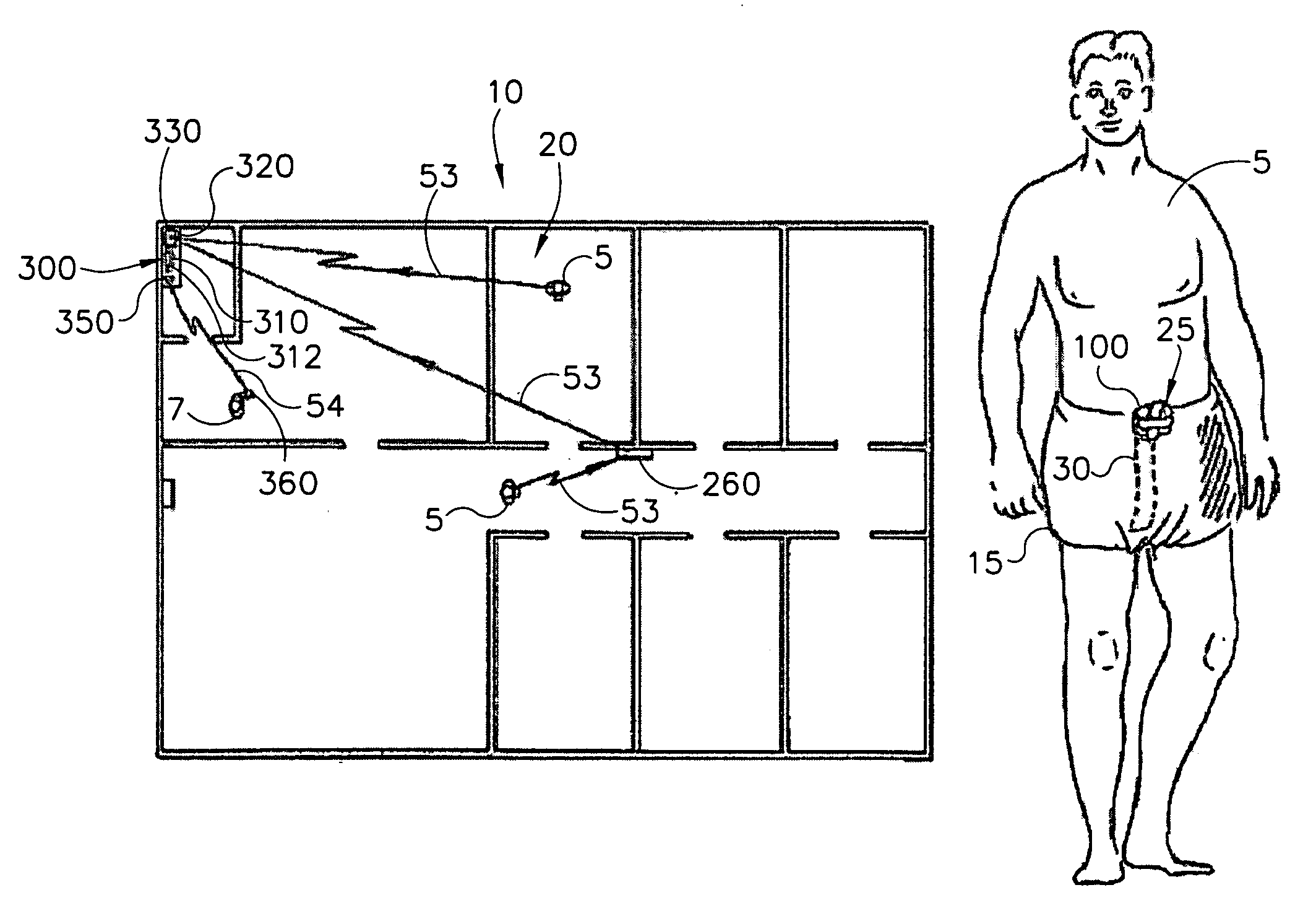
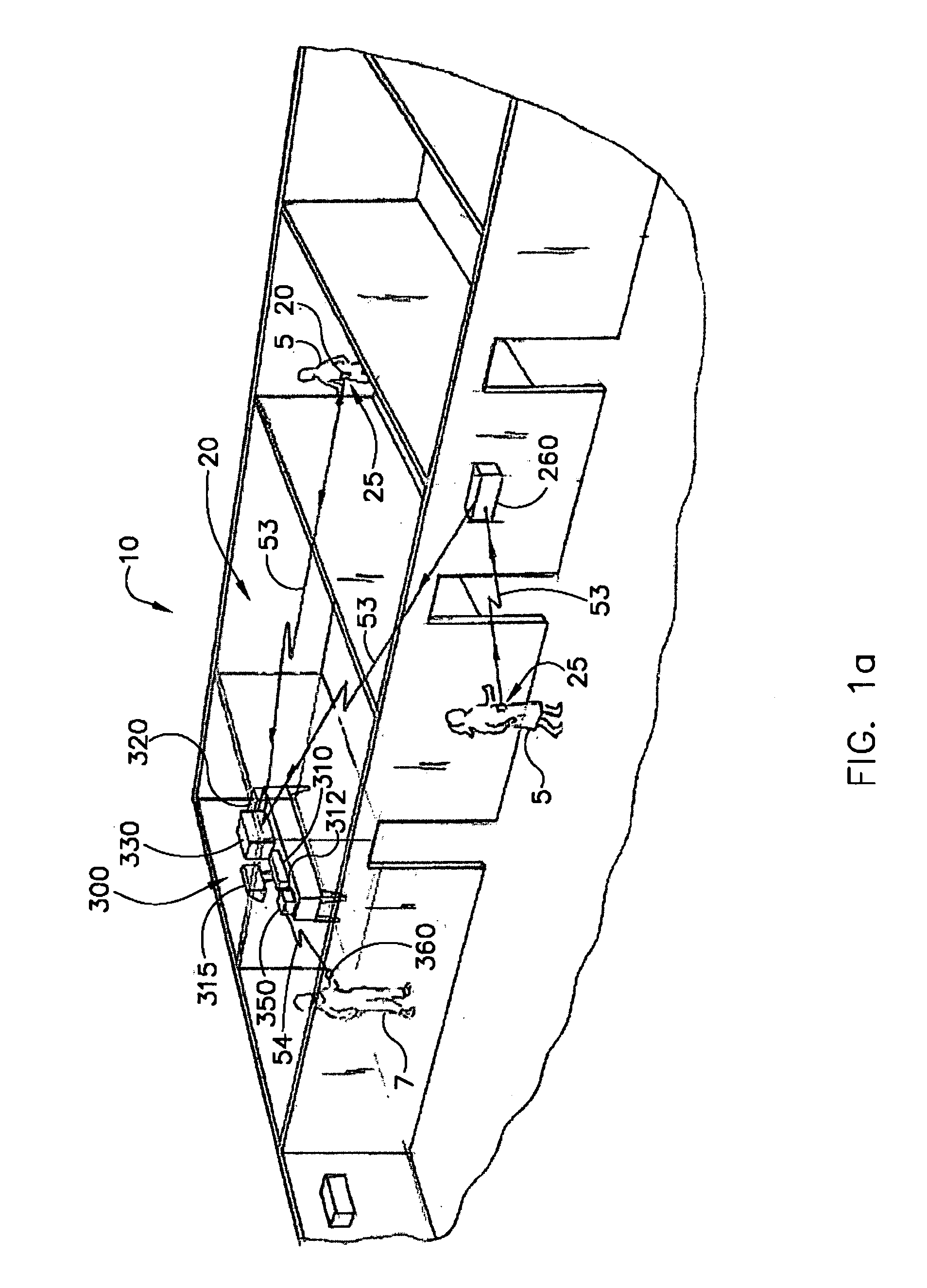
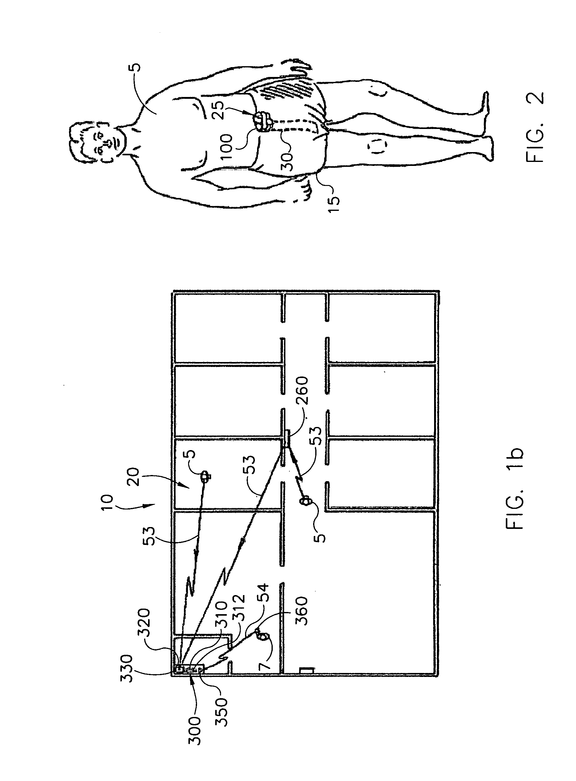
[0046]Many individuals 5 desire or need assistance from healthcare workers 7 such as nurses, nurses aids, nutritionists, cooks, doctors, etc. These individuals live in assisted living or nursing homes 10, and are frequently afflicted with bladder control problems that hinder their ability to notice when their bladder is full or exert the control needed to hold their bladder until they are able to use a bathroom. The consequence of this affliction is that the individual 5 ends up wetting his or her undergarment or diaper 15 worn around the waist and groin of the individual. Ab...


PUM

PropertyMeasurementUnit
length of timeaaaaaaaaaa
lengthaaaaaaaaaa
lengthaaaaaaaaaa

Abstract

The present invention relates to a wetness monitoring system that includes a data collection device that sends wetness measurement data to a central computer that detects changes in wetness measurement data caused by the presence of urine or other dielectric fluids. The data collection device includes a semi-reusable sensor and reusable data collector that are worn on a garment of the person. The data collector includes an internal power source so that the person can live a normal ambulatory life. The data collector has an electrical circuit that uses the changing resistance characteristics in the sensor to gather wetness measurement data. The data collector periodically generates and transmits a signal containing the actual wetness measurement data. The signals are coded to identify the particular data collector or person sending the signal. The data collector is programmed to conserve power by sending signals less frequently during periods when the sensor is clearly dry. Signals are sent more frequently when the sensor is damp or a wetness event may have occurred. The central computer receives the signals containing the wetness measurement data and compares the measurement data to an adjustable wetness sensitivity level to determine if a wetness event has occurred. When the central computer determines that a wetness event has occurred, the computer displays the name of the particular person wearing the data collector and the approximate time that the wetness event occurred. The system then pages an appropriate healthcare worker to inform them that the particular individual needs attention and tracks the approximate response times to ensure that the patient is continuously receiving prompt care.

Description

TECHNICAL FIELD OF THE INVENTION[0001]This invention relates to a wetness monitoring system with a data collection device that attaches to a garment of an individual to gather and transmit wetness measurement data to a central computer system that determines when a wetness event occurs, notifies appropriate healthcare workers, and tracks approximate response times to ensure that the individual is consistently receiving proper care.BACKGROUND OF THE INVENTION[0002]Families, assisted living homes and hospitals continually strive to provide the best care they can for their loved ones, residents and patients. Yet, providing basic care such as feeding, bathing and clothing a person can be time consuming, unpleasant and unrewarding. Perhaps the least favored of these tasks is changing a diaper or garment of a person that has been rendered incontinent. Still, these tasks must be done well and in a timely manner for the person to receive proper care. Products and systems that help deliver a...

Claims


Application Information

Patent Timeline
Patent Type & Authority Patents(United States)
IPC IPC(8): A61F13/15G08B21/00G08B23/00A61F13/42G01N27/12G06F19/00
CPCA61F13/42G01N27/121
Inventor HOFMEISTER, CHRISTOPHER M.LANGE, DAVID A.KENDALL, CHARLES B.SCHMIDT, JOHN G.
Owner RF TECH
Why Eureka
Try Eureka