Hydraulic torque converter

a technology of torque converter and hydraulic pump, which is applied in the direction of fluid coupling, gearing, rotary clutch, etc., can solve the problems of fatigue-induced breakage, excessive stress, cracking of cooperating parts, etc., and achieves the effect of useful li

Inactive Publication Date: 2002-06-20
SCHAEFFLER TECH AG & CO KG
View PDF0 Cites 6 Cited by
  • Summary
  • Abstract
  • Description
  • Claims
  • Application Information

AI Technical Summary

Benefits of technology

[0007] An object of the instant invention is to provide a hydraulic torque converter which is more reliable than heretofore known torque converters and whose useful life is much longer than those of the aforediscussed and other conventional apparatus of such character.
[0008] Another object of the invention is to provide a torque converter which can be assembled and installed in the power train of a motor vehicle or the like in a manner much simpler than conventional torque converters.
[0009] A further object of the present invention is to provide a torque converter which is constructed and assembled with a view to reduce the effects of fatigue upon its useful life and / or upon the reliability of its operation and which is more likely to withstand the effects of unanticipated stresses, hard-to-detect cracks and / or breaks as well as weakening of joints, connections and wear-induced problems than conventional torque converters.

Problems solved by technology

It can happen that the mating gear teeth generate pronounced friction or that they jam.
In fact, the tension between the input of the torsional vibration damper and the piston of the bypass clutch, and / or non-uniform engagement of the piston of the bypass clutch with the friction surface of the housing of the torque converter, can cause the development of excessive stresses, a cracking of cooperating parts and fatigue-induced breaks.
Such undesirable phenomena are particularly likely to develop in the parts which are riveted to each other.
Still further, excessive tension between the piston of the bypass clutch and the input of the torsional vibration damper is likely to develop when the piston is caused to frictionally engage the housing with attendant deformation (particularly in the axial direction of the bypass clutch) when the pressure of hydraulic fluid in the cylinder chamber for the piston increases, i.e., when the piston is called upon to transmit torque from the housing to the output of the torque converter by establishing a direct power transmitting path from the output element of the prime mover, through the housing of the torque converter and to the output of the latter, i.e., by bypassing the pump and the turbine of the torque converter.
The means for preventing such radially outward movements of the springs are costly as well as bulky because they take up room as considered axially as well as radially of the damper.
Such modes of affixing the torque converter to the torsional vibration damper and of mounting the damper in the torque converter are time-consuming and necessitate the hiring of highly skilled artisans.
The situation is complicated because the installation of a torque converter in the power train of a vehicle also invariably necessitates the hiring of highly skilled artisans who are capable of carrying out the above outlined undertakings in addition to centering of cooperating moving (rotary) parts relative to the adjacent part or parts.

Method used


Image

  • Hydraulic torque converter
  • Hydraulic torque converter
  • Hydraulic torque converter

Examples


Embodiment Construction

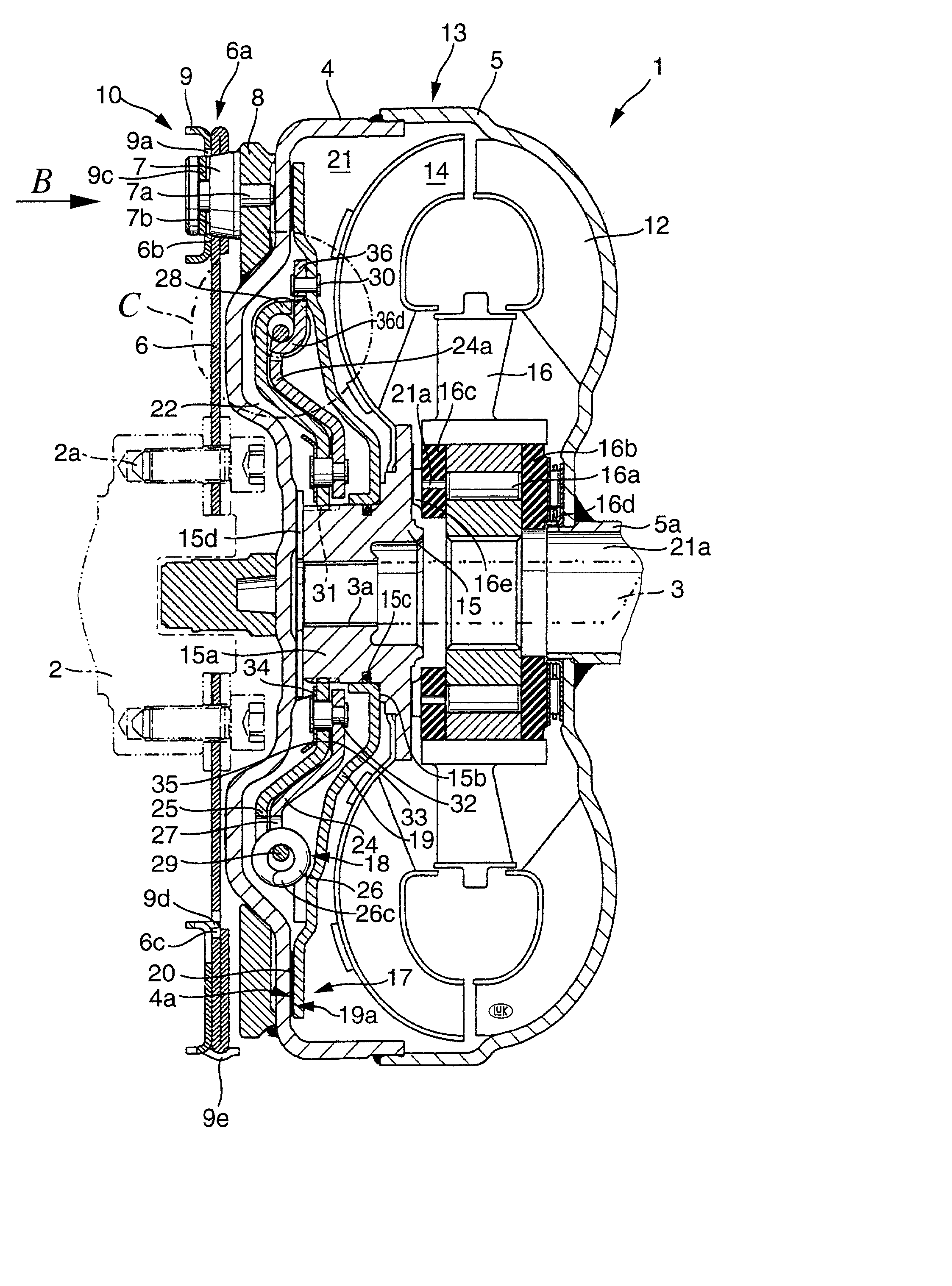
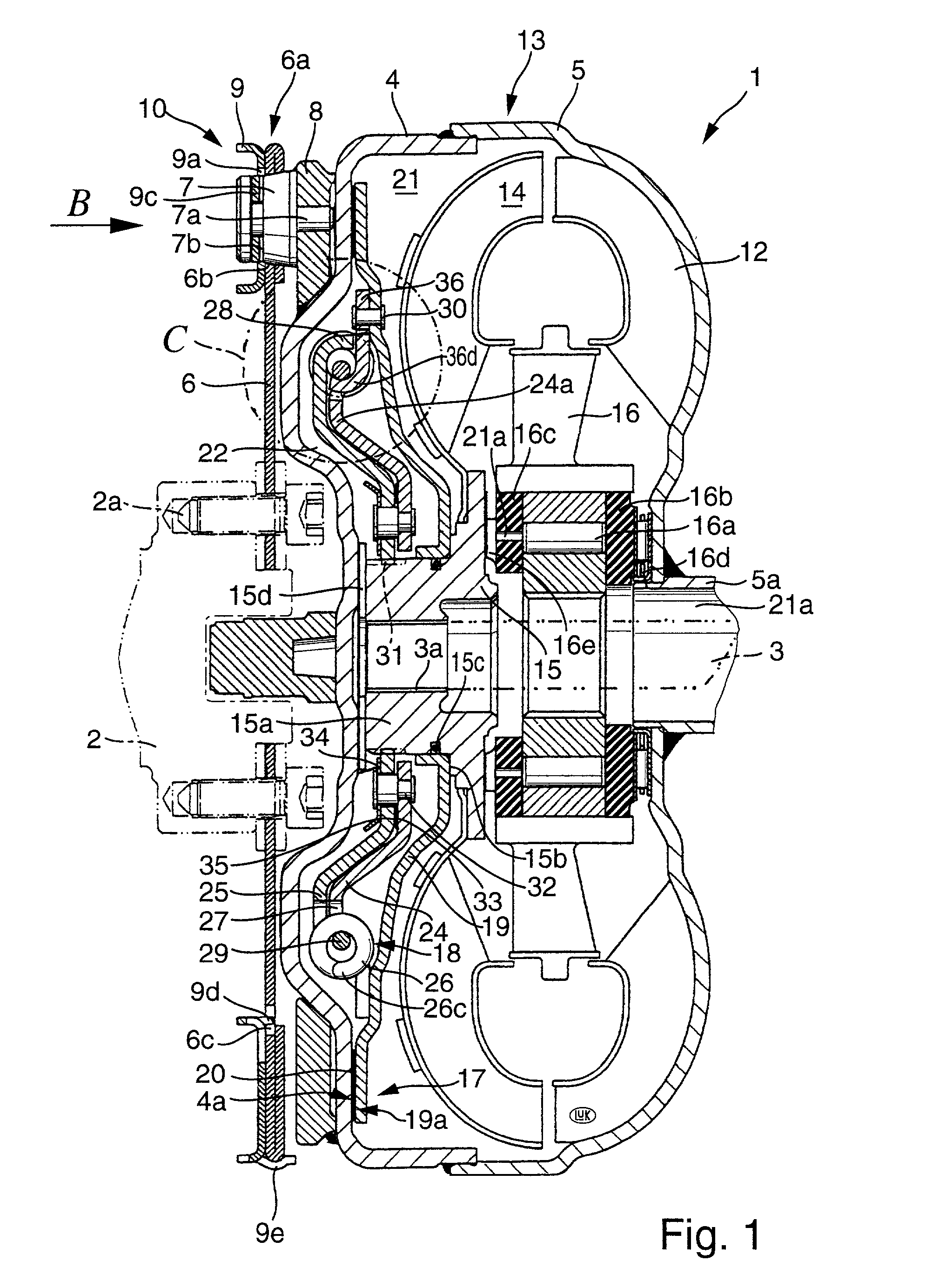
[0069] The hydraulic torque converter 1 which is shown in FIG. 1 comprises a housing 13 which is affixed to the output element 2 of a prime mover, not shown. The output element 2 can constitute the crankshaft of an internal combustion engine in the power train of a motor vehicle; such power train further includes a rotary output element 3 of a change-speed transmission (not shown) which can drive the wheels or certain wheels of the motor vehicle by way of a differential in a manner well known in the art. The torque converter 1 is a fluid-operated clutch which can be utilized in lieu of a dry friction clutch to uncouple the engine in order to stop the motor vehicle in gear or to couple the engine for acceleration. Reference may be had, for example, to pages 691-693 of "Modern Automotive Technology" by James E. Duffy (1994 Edition published by The Goodheart-Willcox Company, Inc., Tinley Park, Ill.). As concerns the operation of a power train which employs a friction clutch, in lieu of...


PUM


Abstract

A hydraulic torque converter, particularly for use in a motor vehicle between the prime mover and the transmission of the power train, employs a combination of a bypass clutch with one or more torsional vibration dampers which brings about savings in space and / or in the number of parts. In addition, the torque converter can stand long periods of use and is less prone to wear, adverse influences of abruptly developing stresses and / or other undesirable influences than conventional torque converters. Furthermore, the improved torque converter employs or can employ a bypass clutch and / or one or more torsional vibration dampers simpler and less expensive than but superior to those in conventional torque converters.

Description

[0001] The invention relates to improvements in torque transmitting apparatus, and more particularly to improvements in hydraulic torque converters which can be utilized with advantage in the power trains of motor vehicles, e.g., between the rotary output element of the prime mover (such as an internal combustion engine) and the input element (such as a shaft) of a change-speed transmission.[0002] A conventional hydrokinetic torque converter in the power train of a motor vehicle normally comprises a housing which shares the angular movements of the output element (such as the crankshaft) of the engine, a pump which shares the angular movements of the housing, a turbine which can receive torque from the housing by way of a body of hydraulic fluid confined in the housing and being circulated by the vanes or blades of the pump, as well as an output member (e.g., a hub) which can receive torque from the turbine to transmit torque to a driven member such as the input shaft of the change-...

Claims


Application Information

Patent Timeline
Patent Type & Authority Applications(United States)
IPC IPC(8): F16H45/02
CPCF16H45/02F16H2045/0294F16H2045/0284F16H2045/021
Inventor BACK, GUNNARMULLER, BRUNOFRIEDMANN, HUBERTMAIENSCHEIN, STEPHAN
Owner SCHAEFFLER TECH AG & CO KG
Why Eureka
Try Eureka