Magnetically coupled drive for a sealed liquid level sender

a magnetic coupling and liquid level technology, applied in liquid/fluent solid measurement, machines/engines, instruments, etc., can solve the problem that the geometrical arrangement does not develop thrust along, and achieve the effect of improving the performance and useful life of such a sensor and increasing the torqu

Active Publication Date: 2010-03-09
COCHRAN IP HLDG LLC +1
View PDF51 Cites 8 Cited by
  • Summary
  • Abstract
  • Description
  • Claims
  • Application Information

AI Technical Summary

Benefits of technology

[0007]The inventor believes that the addition of one or more flux closure elements to a magnetically operated, hermetically sealed, limited sweep in-tank fuel level sensor can provide a significant increase in torque that is important for improving performance and useful life of such a sensor. The inventor further believes that it is desirable to minimize, and preferably substantially eliminate, both axial thrust and radial cross-thrust on bearings or shafts in such sensors.

Problems solved by technology

Furthermore, the geometrical arrangement does not develop thrust along the length direction of the rotation axle.

Method used


Image

  • Magnetically coupled drive for a sealed liquid level sender
  • Magnetically coupled drive for a sealed liquid level sender
  • Magnetically coupled drive for a sealed liquid level sender

Examples


Embodiment Construction

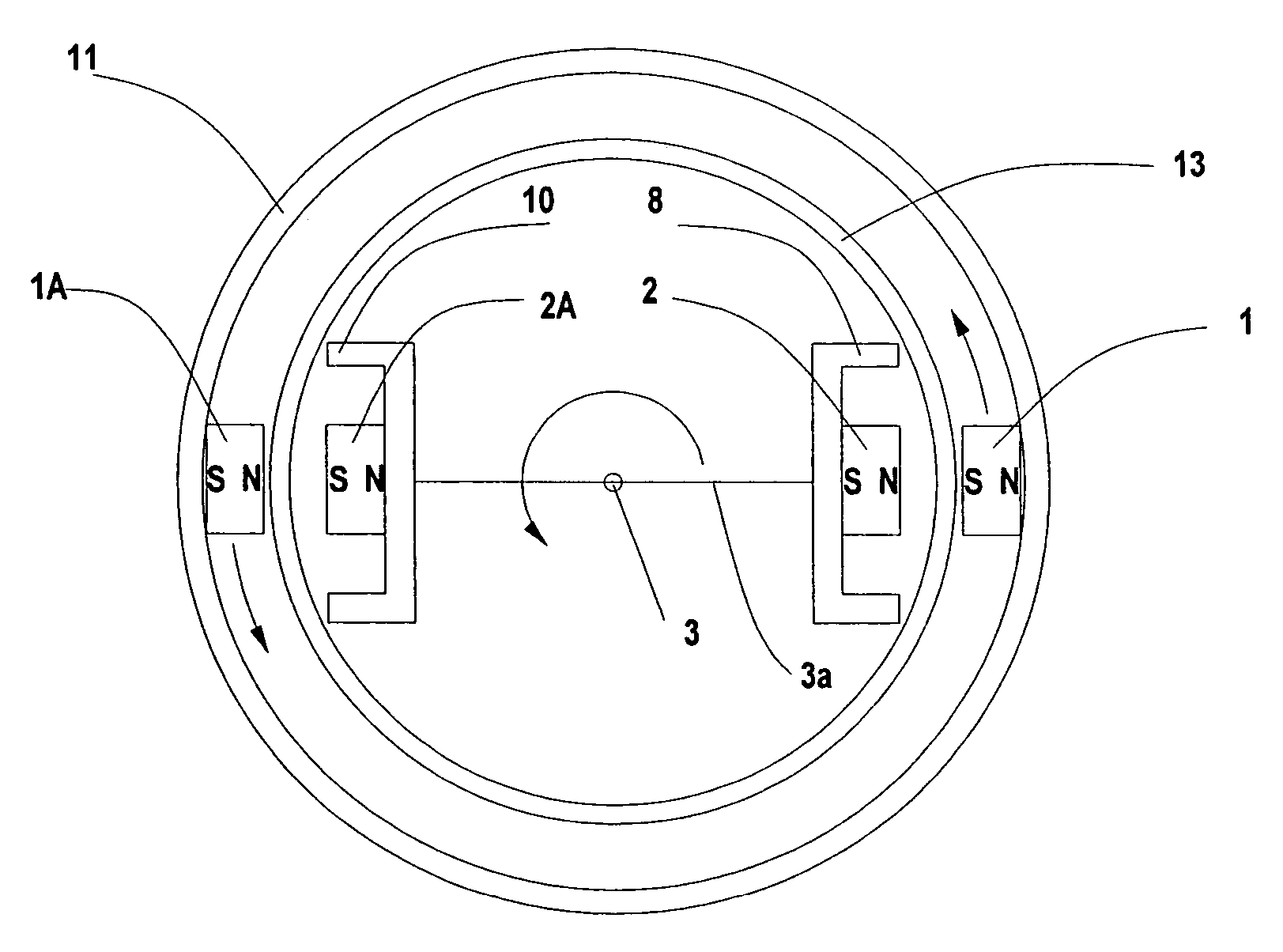
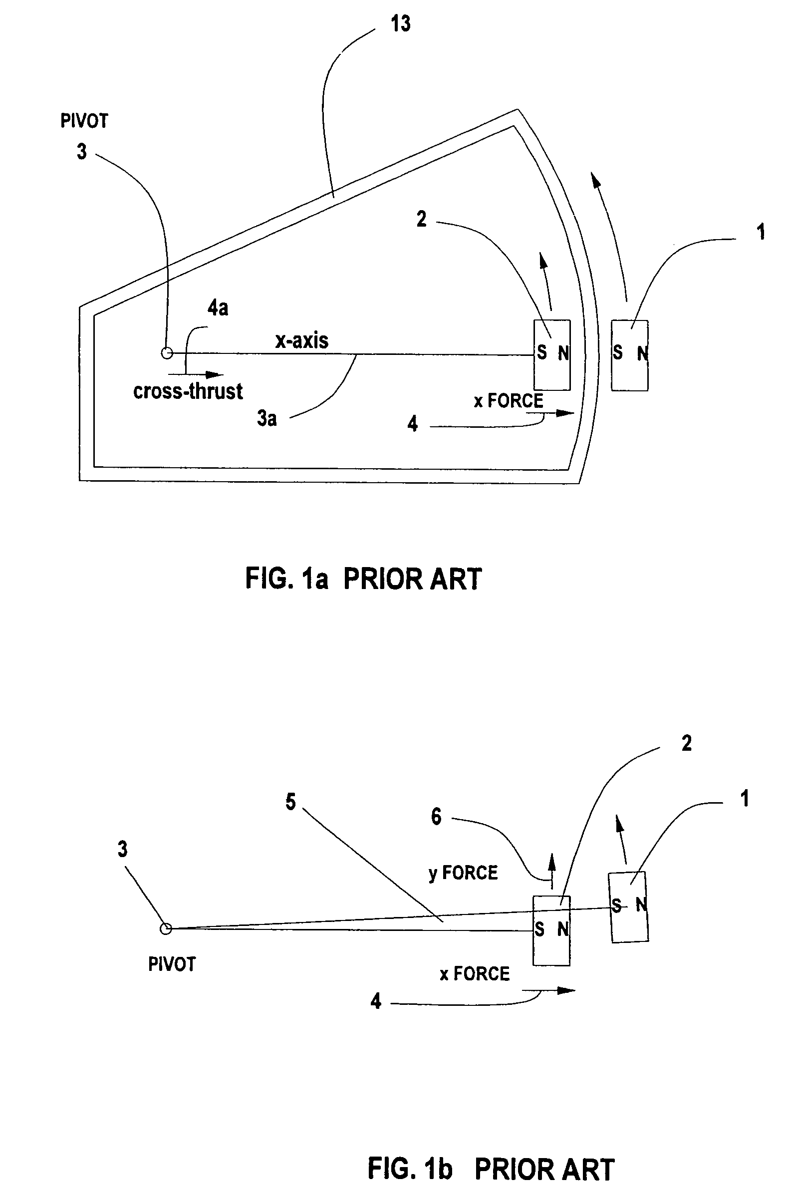
[0015]FIG. 1a shows a prior art design. It's highly asymmetrical and gives rise to a large cross-thrust 4a on an axle, or shaft, at the pivot point 3. Magnet 1 is the driving magnet and magnet 2 is the driven magnet. An axle, not shown, passes through the pivot point in the vertical direction with respect to the drawing sheet, and magnet 2 is connected to the axle by a rod 3a or mounting assembly from pivot 3 to magnet 1. This is shown along the x-axis. A cross-thrust force of 0.5 lbs is easily attained with magnets 1 and 2 made of Neodymium Iron Boron (NEO) in typical design geometries. This can be very stressful on the axle pivot point, causing a shortened lifetime and increased friction. Also, the magnets do not have any flux closure paths, leading to a non-optimum torque with large air gaps. The interior of a sealed chamber is isolated from the outer environment by a closed wall 13, including front and back walls, not shown. At least the portion of wall 13 between the magnets mu...


PUM


Abstract

The internal movement of one embodiment of a sealed fuel level sender employs two magnets disposed diametrically opposite each other about a pivot. The actuator that is operated by in-tank fuel level has two magnets disposed diametrically opposite each other about the axis with one pole of each magnet of the actuator confronting an opposite pole of a respective magnet of the movement to provide the magnetic coupling for causing the movement to follow the fuel level while minimizing, and preferably substantially eliminating, cross thrust on the pivot. Pole pieces may be associated with the magnets in a further embodiment. Still another embodiment employs magnets to only one side of the pivot, but with pole pieces that reduce cross thrust.

Description

REFERENCE TO A RELATED APPLICATION AND PRIORITY CLAIM[0001]This application claims the priority of provisional patent application No. 60 / 756,151, filed Jan. 4, 2006.TECHNICAL FIELD OF THE INVENTION[0002]The present invention is directed to the field of devices whose operating drive function depends upon magnetic coupling between a driven component and a follower component, the two components coupled solely by a magnetic field. In particular, the invention relates to float-operated senders that are associated with fuel tanks of motor vehicles to transmit a value of a parameter representing the level of liquid fuel in a tank to instrumentation that uses the value to operate a display that presents information related to the level of fuel in the tank to a driver of the vehicle, applied to a sealed fuel level sender with a sweep of less than 180 angular degrees.BACKGROUND OF THE INVENTION[0003]Recent development of a fuel level sender with a resistor card inside a sealed chamber is desc...

Claims


Application Information

Patent Timeline
Patent Type & Authority Patents(United States)
IPC IPC(8): G01F23/30
CPCG01F23/38H02K49/106
Inventor COCHRAN, GARY D.
Owner COCHRAN IP HLDG LLC
Why Eureka
Try Eureka