Carburetor fuel adjustment assembly

a carburetor and fuel flow technology, applied in the field of carburetor, can solve the problems of inconvenient assembly, inability to adjust the fuel flow, and excessively rich or lean fuel mixture, so as to improve engine performance and useful life, reduce manufacturing costs and assembly costs, and improve engine control

Active Publication Date: 2007-07-10
WALBRO LLC
View PDF17 Cites 6 Cited by
  • Summary
  • Abstract
  • Description
  • Claims
  • Application Information

AI Technical Summary

Benefits of technology

[0009]Objects, features and advantages of this invention include a carburetor fuel flow adjustment assembly which prevents inadvertent alteration of fuel flow after calibration, after factory installation of limiter caps and / or during user operation, improves engine control, improves engine performance and useful life, provides a compact carburetor design, reduces manufacturing costs and assembly costs, is relatively simple design, robust, inexpensive, requires little to no maintenance and in service has a long useful life.

Problems solved by technology

Fuel flow rate changes caused by this needle “slop or wobble” result in excessively rich or lean fuel mixtures that undesirably increase exhaust emissions or affect engine performance.
Unfortunately, springs 26 are relatively expensive to manufacture, and to produce sufficient frictional forces must be relatively long, causing the needle valves 17 to project a substantial distance outward from an otherwise compact carburetor.
Unfortunately, the retainer clip 27 is external to the carburetor body 19 and thus subject to possible damage.
Unfortunately, manufacture of the fastening member is expensive because after installation into the carburetor body, it must be drilled to produce two axially spaced through-holes and the threads must be formed by the thread rolling.
Moreover, the process of manufacturing the carburetor is restricted because both the receptacles and the fastening member must be machined simultaneously.

Method used


Image

  • Carburetor fuel adjustment assembly
  • Carburetor fuel adjustment assembly
  • Carburetor fuel adjustment assembly

Examples


Embodiment Construction

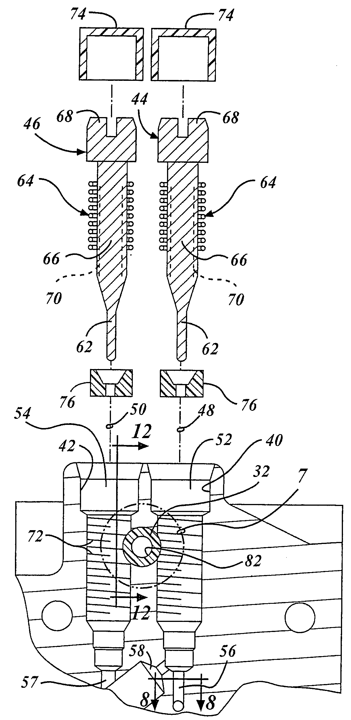
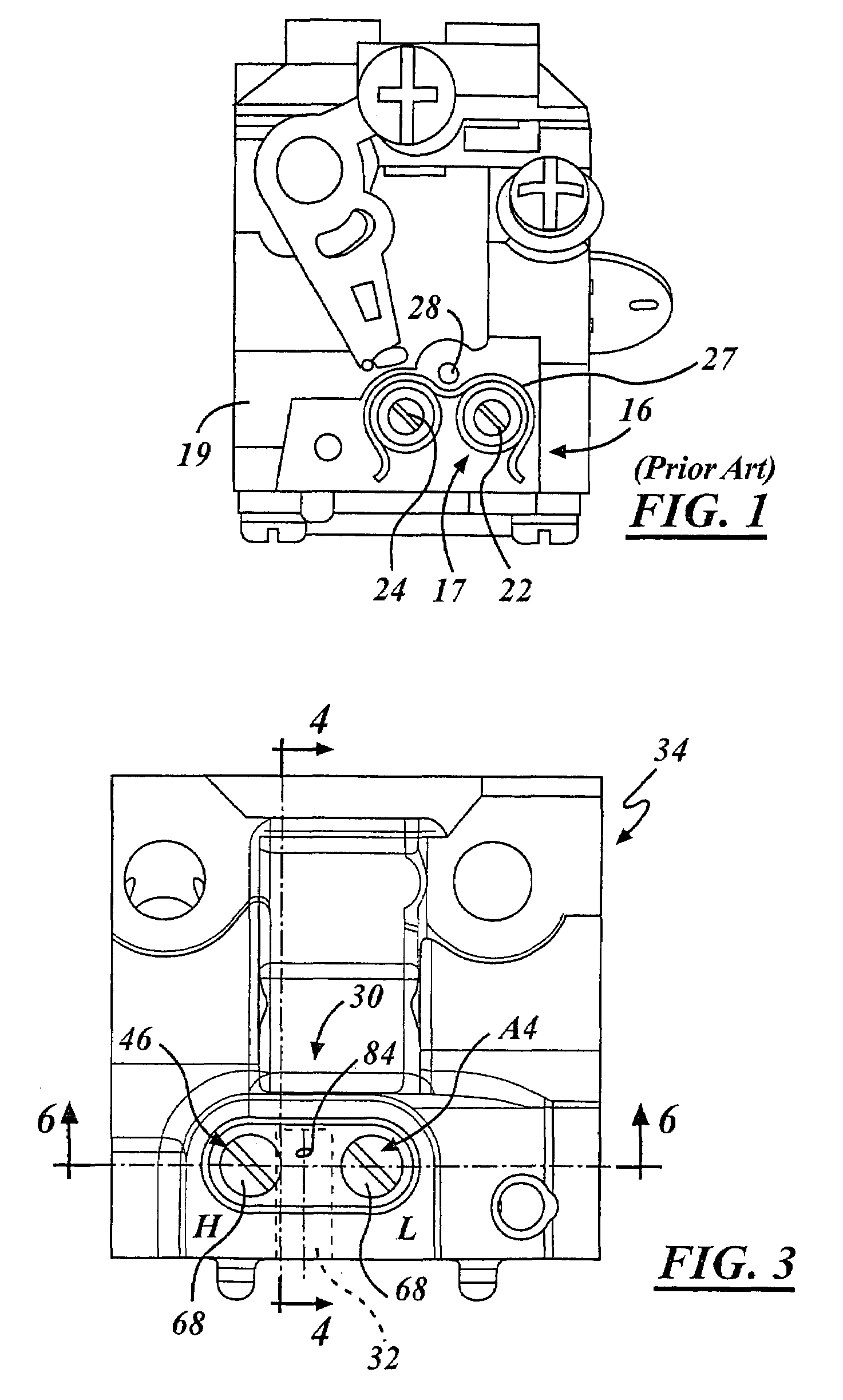
[0023]Referring in more detail to the drawings, FIGS. 3–6 illustrate a carburetor with an adjustable needle valve and retainer assembly 30, embodying the present invention. The fuel adjustment or needle valve assembly 30 controls fuel flow in a carburetor 34 for a combustion engine which is typically a gasoline powered two or four stroke spark ignition internal combustion engine. The carburetor 34 has a fuel-and-air mixing passage 36 through a carburetor body 38 and individually adjustable low and high speed needle valves 44, 46 each received in an associated receptacle 40, 42 in the carburetor body. The valves are threadably received in separate associated cavities 52, 54 each of which communicates with a separate coaxial fuel orifice or seat 56, 57 each disposed in a separate fuel passage 58 which communicates with the fuel-and-air mixing passage 36 to deliver fuel to the mixing passage. In operation liquid fuel is supplied to each cavity 52, 54 upstream of its orifice 56, 57 from...


PUM

PropertyMeasurementUnit
inner diameteraaaaaaaaaa

Abstract

A carburetor fuel adjustment assembly includes a low speed needle valve and preferably a high speed needle valve threaded into respective receptacles of a carburetor body. Each receptacle defines an elongated cavity which intersects a fuel passage and has a valve orifice or seat. Each needle valve has a shank which threadably engages the respective receptacles and a tip that extends into the axially-aligned orifice or seat. The tip is axially movable relative to the orifice by rotation of the needle valve to control the size of the opening between the valve and orifice for fuel flow. A resilient body cooperates with the valve shank in laterally biasing the tip into a steadfast position relative to the orifice or seat. The lateral bias assures constant area for fuel flow through the orifice by resisting needle movement until a sufficient torque is intentionally applied to the needle valve.

Description

FIELD OF THE INVENTION[0001]This invention relates generally to a carburetor and more particularly to a fuel flow adjustment assembly of a carburetor for a combustion engine.BACKGROUND OF THE INVENTION[0002]As shown in FIGS. 1 and 2, a known prior art carburetor has a fuel adjustment assembly 16 with low and high speed adjustable needle valves 17, each threaded into a needle valve receptacle 18 in a carburetor body 19. To permit adjustment of fuel flow, each valve receptacle 18 communicates with a separate fuel passage (not shown) in the carburetor body. Each needle valve 17 generally includes a distal tip 21, an enlarged head 22 and a threaded shank 23 disposed between the tip and the enlarged head. The threaded shank 23 of the needle valve 17 engages a female threaded portion 20 of the needle valve receptacle 18. The tip 21 of the valve 17 may be positioned within an axially-aligned needle seat orifice of the fuel passage and can be axially advanced and retracted, by rotation of t...

Claims


Application Information

Patent Timeline
Patent Type & Authority Patents(United States)
IPC IPC(8): F02M3/08
CPCF02M3/10Y10S261/38Y10S261/84
Inventor GLINIECKI, GARY U.WHITTAKER, LARRY D.ZBYTOWSKI, ERIC G.
Owner WALBRO LLC
Why Eureka
Try Eureka