Hoisting mechanism for steel processing ladles in RH degassers

a technology of rh degasser and steel processing ladle, which is applied in the direction of manufacturing converters, transportation and packaging, manufacturing tools, etc., can solve the problems of large space, vertical movement, and correspondingly large capital investment, and achieve the effect of shortening the process cycle time and facilitating the operation sequen

Inactive Publication Date: 2007-12-06
SIEMENS VAI METALS TECHNOLOGIES GMBH & CO
View PDF5 Cites 10 Cited by
  • Summary
  • Abstract
  • Description
  • Claims
  • Application Information

AI Technical Summary

Benefits of technology

[0024] To facilitate the operating sequences and to shorten the process cycle times, pursuant to an embodiment of the invention the transverse connection support can extend over the ladle transfer vehicle at su

Problems solved by technology

However, this has the drawback that the vacuum treatment tank has numerous connections for the vacuum generation and for conducting treatment gasses through and for withdrawing them, so that each movement of the vacuum treatment tank means a corresponding stress upon its connections and the lines connected thereto.
Such crane cable suspension means, and also hydraulic lifting mechanisms, unfortunately require a lot of space and therefore require a co

Method used


Image

  • Hoisting mechanism for steel processing ladles in RH degassers
  • Hoisting mechanism for steel processing ladles in RH degassers
  • Hoisting mechanism for steel processing ladles in RH degassers

Examples


Embodiment Construction

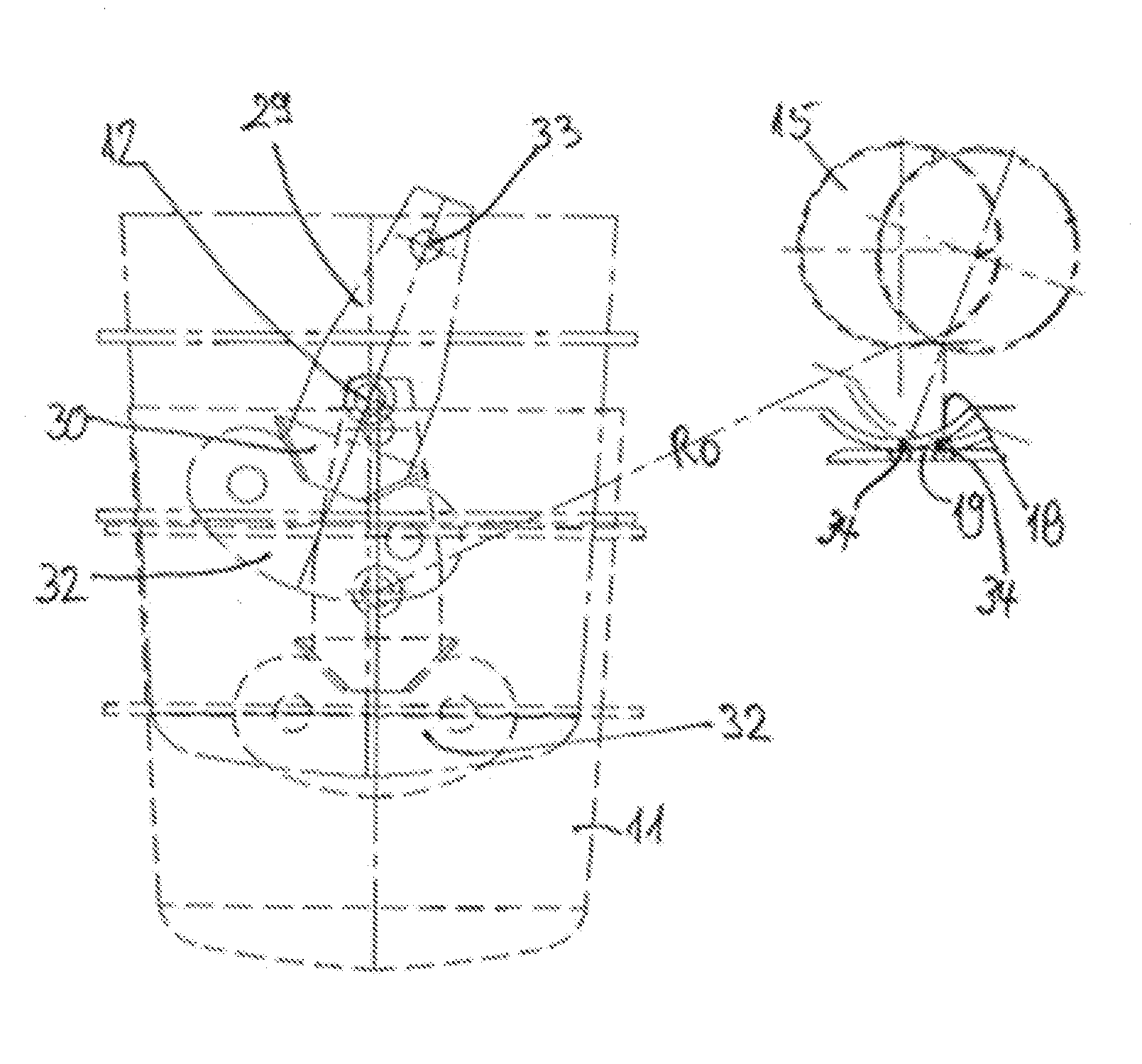
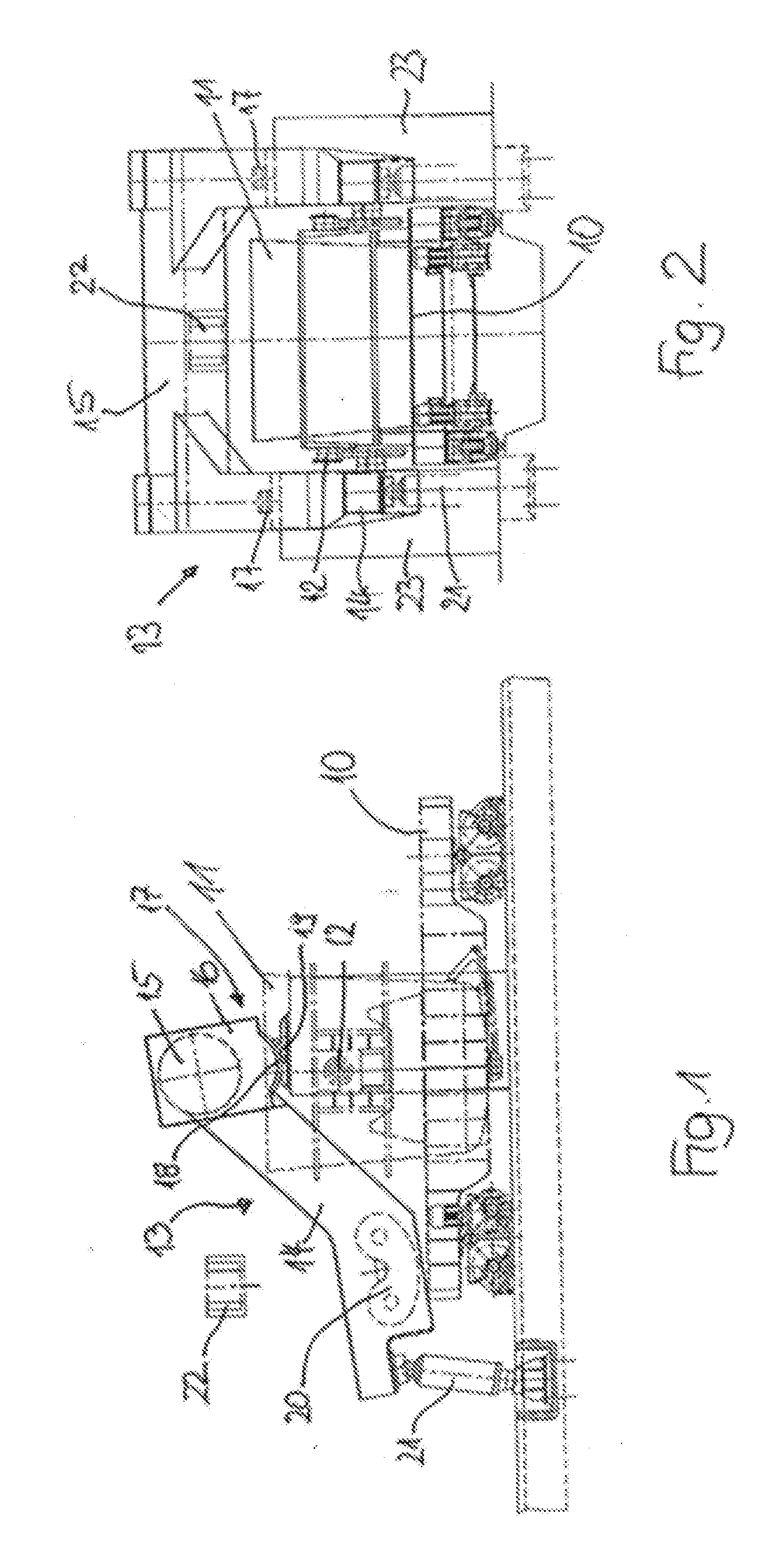
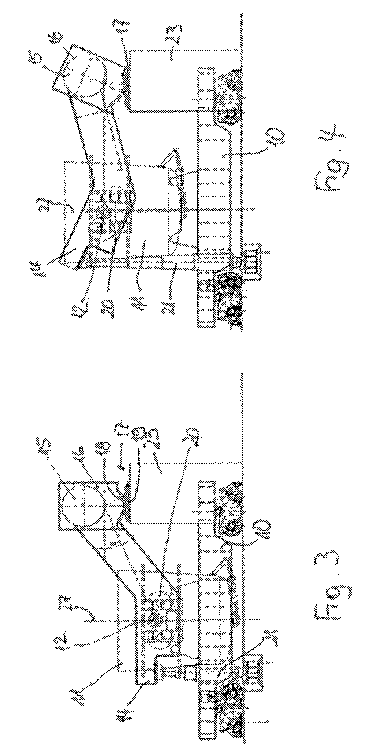
[0028] Referring now to the drawings in detail, as shown initially in FIGS. 1 and 2, a ladle transfer car or vehicle 10 serves for the transport of a ladle 11; during handling of the ladle 11, it is supported on the transfer vehicle 10. For the engagement of handling devices during the normal operational sequence, in the illustrated embodiment the ladle 11 is provided with laterally projecting trunnions 12 as a holding device, so that, for example, crane hooks can engage the trunnions 12 of the ladle 11.

[0029] The reference numeral 13 designates a hoisting mechanism for the ladle 11 by means of which the ladle can be raised to only schematically illustrated immersion tubes or pipes 22 of a not further illustrated vacuum treatment tank. The hoisting mechanism 13 is comprised of two lifting arms 13, which car) engage the trunnions 12 of the ladle 12 on both sides. As can be seen by looking at FIGS. 1 and 2, the two lifting arms 14 are connected to one another by means of a transverse...


PUM

PropertyMeasurementUnit
Heightaaaaaaaaaa
Strengthaaaaaaaaaa

Abstract

A hoisting mechanism for raising a ladle filled with liquid steel from a transfer vehicle to immersion pipes of a vacuum treatment tank of an RH degasser. Two lifting arms are provided, one end of which can be brought into engagement with a support device formed on the ladle, and a bearing end of the arms is supported in a stationary saddle support comprised in such a way of a runway, disposed on the bearing ends of the lifting arms and having the shape of a circular arc, and of a path of rolling contact, adapted to axially fixedly guide the runway during pivoting of the lifting arms, that due to shifting of the point of load introduction in the saddle support occurring during a raising movement, reduction of a horizontal movement of the ladle occurs.

Description

[0001] The instant application should be granted the priority date of Jun. 2, 2006 the filing date of the corresponding German patent application 10 2006 026 330.8-24. BACKGROUND OF THE INVENTION [0002] The present invention relates to a hoisting mechanism for raising a ladle filled with liquid steel from a ladle transfer vehicle to the immersion pipes of the vacuum treatment tank of an RH degasser. [0003] In a so-called RH degasser, liquid steel is subjected to a vacuum treatment by immersing the immersion pipes of the vacuum treatment tank into the liquid steel that is disposed in the ladle. To keep the treatment times short, the requirement exists to design the diameter of the immersion pipes as large as possible in correspondence to the ladle dimensions. In operational practice, for this purpose in one embodiment the vacuum treatment tank is lowered into the ladle, which rests upon a ladle transfer vehicle. However, this has the drawback that the vacuum treatment tank has numero...

Claims


Application Information

Patent Timeline
IPC IPC(8): C21C5/46
CPCB22D41/12B66C17/10C21C7/10C21C7/0075C21C5/4633
Inventor EHLE, JOACHIM K.HUELLEN, MARKUSKURLBAUM, MICHAELPANNENBACKER, REINHARDLUVEN, ARNOSOWINSKI, JOOHEN
Owner SIEMENS VAI METALS TECHNOLOGIES GMBH & CO
Why Eureka
Try Eureka