
Exterior Sliding Door for a Vehicle

a vehicle door and exterior technology, applied in the direction of doors, roofs, wing accessories, etc., can solve the problems of guide rails occupying a particularly large volume, guide rails being exposed, bottom rails being damaged, etc., and achieve the effect of easy access and small investmen

Inactive Publication Date: 2007-12-06
DAIMLER AG
View PDF6 Cites 10 Cited by
  • Summary
  • Abstract
  • Description
  • Claims
  • Application Information

AI Technical Summary

Benefits of technology

[0006] An example embodiment of the present invention may provide a sliding exterior vehicle door such that, in combination with little outlay on construction, easy accessibility to the vehicle interior may be made possible without impairing the body surface.
[0007] According to an example embodiment of the present invention, an exterior vehicle door is guided displaceably in guide rails, there being provided at least one guide rail which is mounted fixedly on the vehicle body and a further guide rail which is being designed as a door guide rail and arranged on the vehicle door. The guide rail mounted fixedly on the vehicle body includes a first section extending diagonally to the door plane and via which the door is lifted, upon opening, out of its position in which it is flush with the remainder of the body. In a second section extending approximately parallel to the door plane, the vehicle door may be slid along outside the body into its fully opened position. The body-mounted door rail is arranged in the region of an upper edge of the vehicle door and the door guide rail provided on the vehicle door is arranged in the region of its lower edge and, e g., integrated into this edge. This may ensure that the body-mounted door rail is arranged outside of the stepping and loading region and is not susceptible to damage and soiling.
[0008] The arrangement of the door guide rail in the region of the lower door edge results in the lower edge of the door opening being free of any guide rails. A step, and if appropriate the floor behind it too, may be lowered by about, e.g., 40 mm to 70 mm, thereby facilitating access and reducing loading on or damage to the opening frame in this region. The arrangement of the door-mounted door guide rail on the lower edge of the guide rail may not impair the structure of the door. An inner shell of the door may be constructed continuously in a cost-saving manner with high surface load-bearing capacity. The door rail is arranged outside an internal access region, thereby reducing the risk of damage. The visual appearance of the inner side of the door is not impaired, making it possible to dispense with complicated coverings, etc.

Problems solved by technology

Such guide rails take up a particularly large volume.
For a relatively low floor, they protrude beyond the latter and constitute an obstacle when getting in and out or during loading and / or unloading.
The bottom rail may be damaged as a result of being stood upon or coming into contact with bulky goods.
The interior of the guide rail is exposed to considerable soiling via its open side, with cleaning being possible only with difficulty due to poor accessibility.
The visual appearance of the body surface is disrupted, with, in particular, the legibility of any applied lettering, logos, company advertising, etc. being impaired.
The operation of covering the slot by the peripheral band is complicated.
The inner door shell is interrupted in the region of the rail, thereby impairing both its load-bearing capacity and its visual appearance.
At least one body-mounted guide rail may be arranged behind a lateral window pane, with the result that the guide rail is not arranged within the region of vision.

Method used


Image

  • Exterior Sliding Door for a Vehicle
  • Exterior Sliding Door for a Vehicle
  • Exterior Sliding Door for a Vehicle

Examples


Embodiment Construction

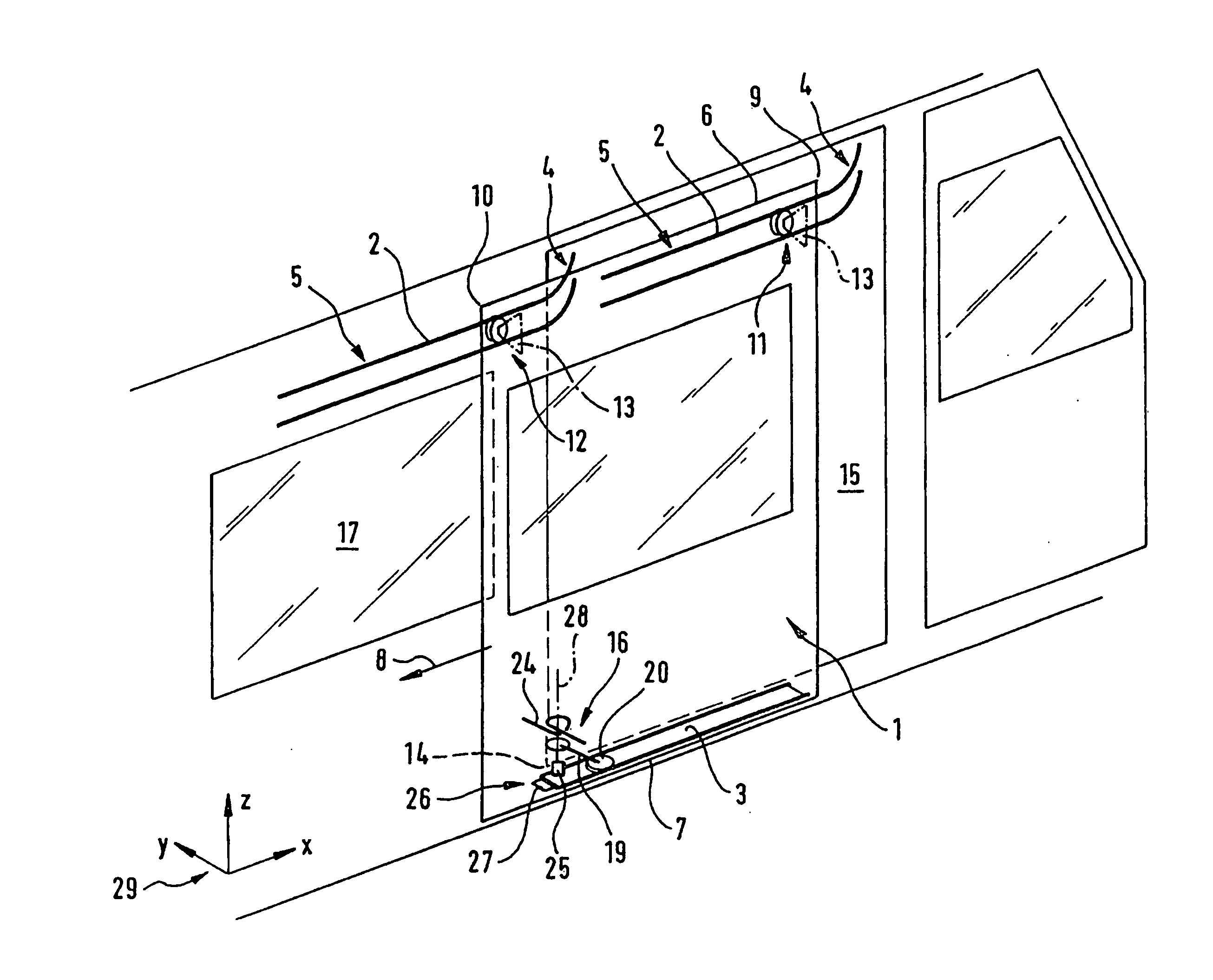
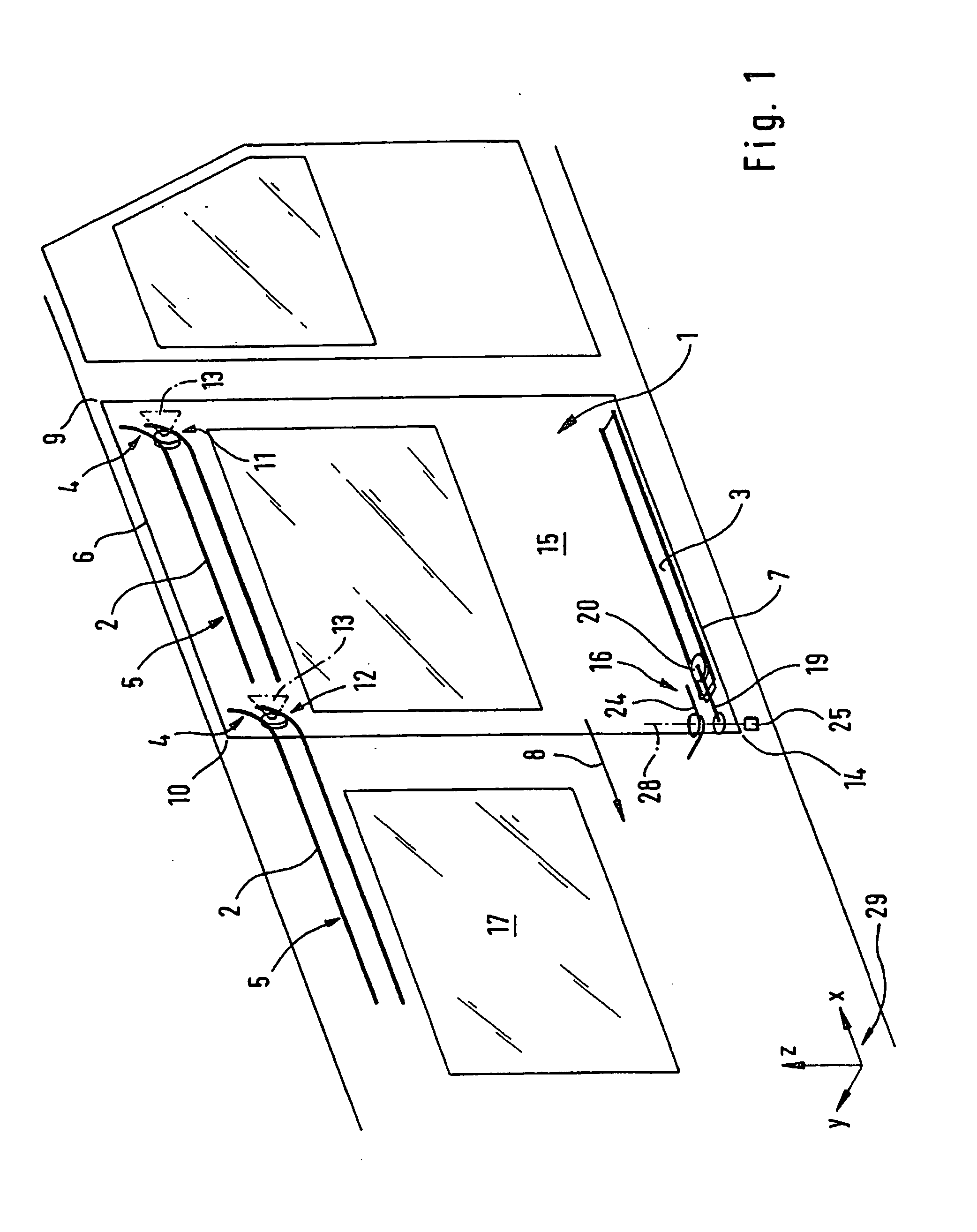
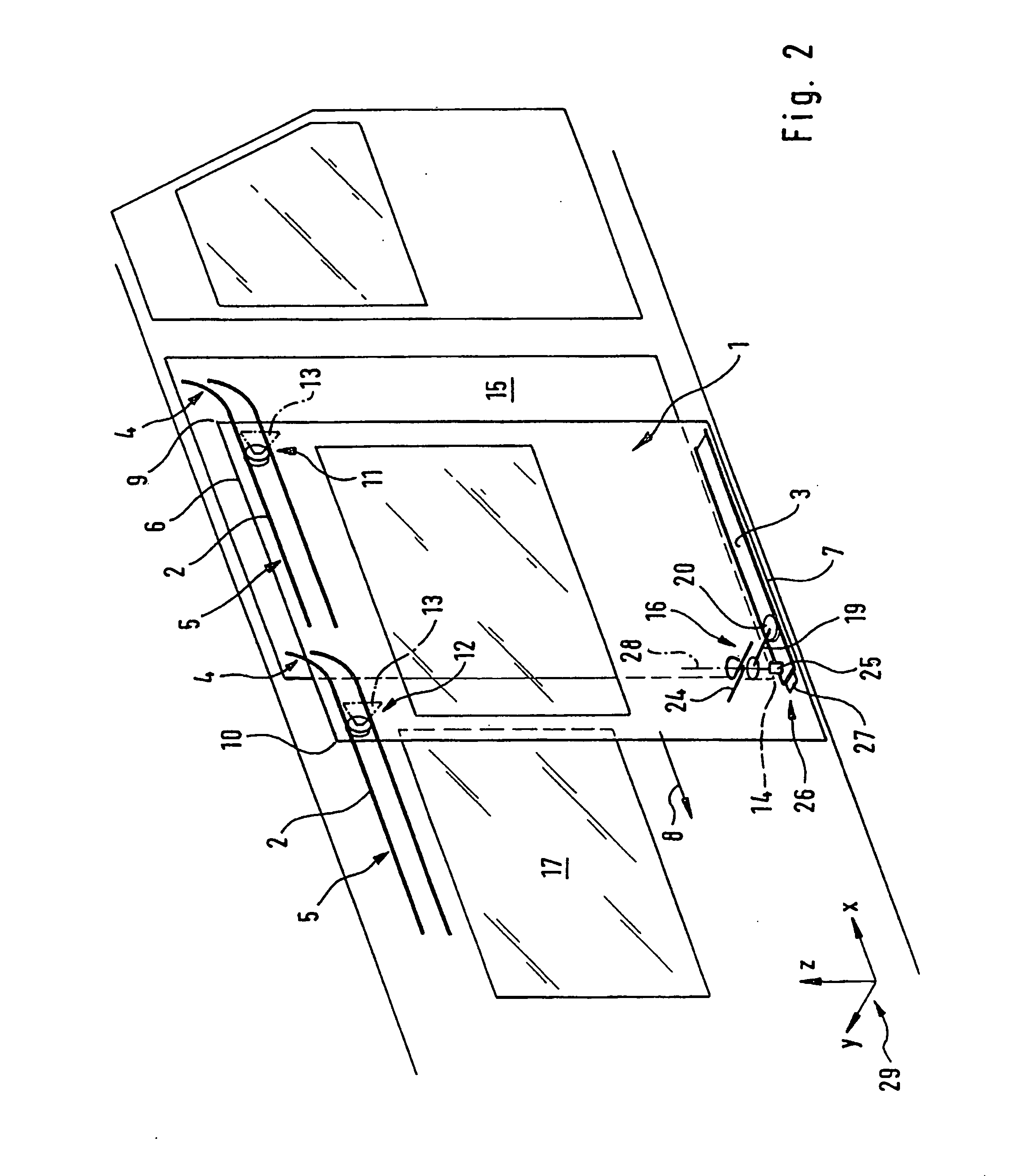
[0023]FIG. 1 is a perspective schematic view illustrating the outer side wall of a motor vehicle having a sliding exterior vehicle door 1. The vehicle door 1 is guided displaceably in guide rails 2, 3, with two body-mounted door rails 2 being arranged in the region of an upper edge 6 of the vehicle door 1. A door guide rail 3 integrated into the vehicle door 1 is arranged in the region of a lower edge 7 of the vehicle door 1. The two guide rails 2 mounted fixedly on the body each have a first section 4 extending diagonally to the door plane and, adjoining this first section, a second section 5 extending approximately parallel to the door plane.

[0024] The vehicle door 1 may be slid open from the closed position indicated in an opening direction indicated by an arrow 8. At the same time, a door opening 15 which may be closed by the vehicle door 1 is revealed. The vehicle door 1 has, with respect to the opening direction 8, a front upper corner 9 and a rear upper corner 10, whereas th...


PUM


Abstract

An exterior vehicle door is guided in a sliding manner in guide rails. At least one guide rail is provided which is mounted fixedly on the vehicle body and which includes a first section extending diagonally to the door plane and a second section extending approximately parallel to the door plane. A door guide rail is arranged on the vehicle door in the region of its lower edge. The body-mounted door rail is arranged in the region of an upper edge of the vehicle door.

Description

FIELD OF THE INVENTION [0001] The present invention relates to a sliding exterior vehicle door. BACKGROUND INFORMATION [0002] Small and medium-size transportation vehicles are provided at their side with a displaceable exterior vehicle door by which a loading space is conveniently accessible from the edge of a curb, for example. Relatively large passenger vehicles, often referred to as vans, are provided in some versions with such lateral exterior sliding doors, which allow easy access to the rear seats of the vehicle. The displaceable exterior doors are guided in guide rails, with one guide rail, which is mounted fixedly on the vehicle body, extending in the floor region of the vehicle. This guide rail includes a first section extending diagonally to the door plane and a second section extending approximately parallel to the door plane. In the closed state, the exterior vehicle door is arranged flush with the remainder of the body. Upon opening, the door is pushed diagonally outwar...

Claims


Application Information

Patent Timeline
IPC IPC(8): B60J5/06E05D15/06E05D15/10E05F1/08
CPCB60J5/06E05D15/1047E05D15/1081E05Y2900/531E05D2015/1086E05F1/16E05D2015/1055
Inventor MUELLER, JENS
Owner DAIMLER AG
Learn More