Rotor for motors

a rotor and motor technology, applied in the direction of rotating magnets, magnetic circuit rotating parts, synchronous machines with stationary armatures, etc., can solve the problems of increased torque ripple, rapid decrease of torque, and inability to equip the first and second divided rotor magnetic pole units, so as to suppress the increase in higher harmonic iron loss, reduce the control accuracy of the motor, and suppress the effect of controlling malfunction

Inactive Publication Date: 2007-12-06
SANYO DENKI CO LTD
View PDF9 Cites 8 Cited by
  • Summary
  • Abstract
  • Description
  • Claims
  • Application Information

AI Technical Summary

Benefits of technology

[0020]It is preferred that a protective layer is provided on outer circumferential surfaces of the first and second rotor magnetic pole units. The protective layer is formed by winding a yarn made of a reinforced fiber material around the outer circumferential surfaces, and impregnating the yarn with an adhesive agent to fix the yarn thereto. With this arrangement, even when the rotor magnetic pole is formed by the two (the first and the second) divided rotor magnetic pole units, the protective layer may prevent the divided rotor magnetic pole units from coming off from the rotor core due to centrifugal force even at high speed rotation.
[0021]Especially, the suppressive effect of the disturbance of the flux density wave, which has been attained in the present invention, is remarkably exhibited in a high speed rotary motor, in which detection of the magnetic pole position substantially influences the control of the motor. The high speed rotary motor is defined as a motor in which the rotary shaft rotates at a high speed of 150,000 rotations per minute or more. In such high speed rotary motor, since deterioration of the detecting accuracy of the magnetic pole position caused by the disturbance of the flux density wave greatly reduces the control accuracy of the motor, the effect attained in the present invention is very remarkable.
[0022]In a permanent magnet rotary motor provided with the rotor for motors of the present invention, a Hall element for detecting a magnetic pole position for the rotor for motors is disposed to measure leakage flux leaking out of the permanent magnet magnetic pole portion of the second kind. With this arrangement, as mentioned above, the disturbance of the magnetic flux is hardly generated in the flux density wave detected by the Hall element for detecting a magnetic pole position, and the waveform of the flux density wave is close to a sine wave to suppress malfunction in controlling the motor.
[0023]According to the rotor for motors of the present invention, reluctance torque is generated in the salient pole portion by disposing the salient pole portion in the first divided rotor magnetic pole unit, and an increase in higher harmonic iron loss may be suppressed. In the second divided rotor magnetic pole unit, since the permanent magnet magnetic pole portions of the second kind are disposed adjacent to each other, lowering of motor torque may be suppressed. Moreover, in the present invention, the spacer made of a soft magnetic material is inserted in the gap formed due to size precision of the permanent magnet magnetic pole portion between two adjacent permanent magnet magnetic pole portions of a plurality of the permanent magnet magnetic pole portions in the second divided rotor magnetic pole unit. The soft magnetic material has small retention but large relative magnetic permeability (small magnetic resistance). By disposing the spacer made of the soft magnetic material in the gap between permanent magnet magnetic pole portions, the magnetic resistance in the gap may be reduced. Consequently, disturbance of the flux density wave of the leakage flux leaking out of the second divided rotor magnetic pole unit may be suppressed to make the waveform of the flux density wave closer to a sine wave. As a result, lowering of detecting accuracy of the magnetic pole position may be suppressed.

Problems solved by technology

However, a motor which employs a rotor of this kind has the following problems: high-frequency current ripples are generated by carrier frequency of an inverter to induce higher harmonic iron loss in a stator core and a permanent magnet of the motor, and what is more, torque ripples are increased.
This leads to a rapid decrease in torque.
However, the rotor shown in this publication is not equipped with first and second divided rotor magnetic pole units.
Accordingly, the flux density wave may hardly be formed in a waveform of sine wave, causing a detection error of the magnetic pole position.
Also in the rotor for motors disclosed in Patent Reference 2, disturbance of magnetic flux may occur in the vicinity of the zero crosses of the flux density wave and the wave may hardly be formed in a sine wave, possibly causing malfunction.

Method used


Image

  • Rotor for motors
  • Rotor for motors
  • Rotor for motors

Examples


Embodiment Construction

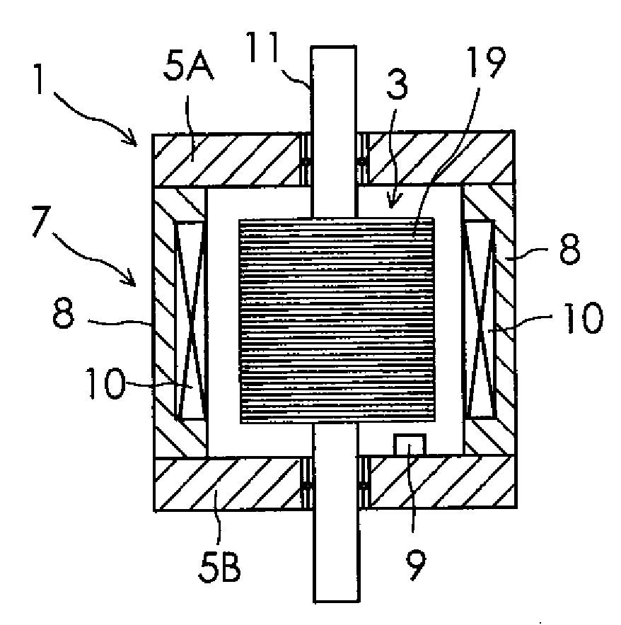
[0045]Preferred embodiments of the present invention will now be described in detail with reference to the drawings. FIG. 1 is a partial cross-sectional view of a permanent magnet rotary motor according to one embodiment of the present invention. In the figure, the rotor for motors is drawn in a top plan view, and other portions are drawn in a cross-sectional view for easier understanding. As shown in FIG. 1, the motor of the present embodiment includes a stator 1 for motors and a rotor 3 for motors. The stator 1 has a pair of brackets 5A, 5B, and an armature 7. The pair of brackets 5A, 5B rotatably supports the rotor 3. A Hall element 9 for detecting a magnetic pole position for the rotor 3 is attached to one bracket 5B of the pair of brackets 5A, 5B. The Hall element 9 for detecting a magnetic pole position is disposed about 1 mm apart from an edge of a permanent magnet magnetic pole portion of a second kind 25, which will be described later, in order to detect leakage flux leakin...


PUM


Abstract

The present invention provides a rotor for motors, in which motor torque is kept high and generation of torque ripples is reduced, and what is more, detecting accuracy of a magnetic pole position is not deteriorated.
A first divided rotor magnetic pole unit 15 and a second divided rotor magnetic pole unit 17 are disposed side by side on a surface of a rotor core 13 in an axial direction of a rotary shaft 11. The first divided rotor magnetic pole unit 15 includes P (P is a positive even number) permanent magnet magnetic pole portions 21 of a first kind and P (P is the positive even number) salient pole portions 23 made of a magnetic material, which are alternately disposed in a circumferential direction of the rotary shaft 11. The second divided rotor magnetic pole unit 17 includes P (P is the positive even number) permanent magnet magnetic pole portions 25 of a second kind which are spaced on another part of the surface of the rotor core 13 in the circumferential direction of the rotary shaft 11. A spacer 27 made of a soft magnetic material is disposed in a gap, which is formed due to manufacturing size precision of the permanent magnet magnetic pole portion, between two adjacent permanent magnet magnetic portions of the P permanent magnet magnetic pole portions of the second kind.

Description

FIELD OF THE INVENTION[0001]The present invention relates to a rotor for motors.BACKGROUND OF THE INVENTION[0002]A conventional rotor for motors is equipped with P (P denotes a number and in this example, P is two) permanent magnets 101 which are disposed on a surface of a rotor core disposed on a rotary shaft in a circumferential direction of the rotary shaft and arranged to be adjacent to each other, as shown in FIG. 18. However, a motor which employs a rotor of this kind has the following problems: high-frequency current ripples are generated by carrier frequency of an inverter to induce higher harmonic iron loss in a stator core and a permanent magnet of the motor, and what is more, torque ripples are increased. At high speed rotation, so-called field-weakening control is carried out to suppress an increase in induction voltage by advancing a current phase angle. This leads to a rapid decrease in torque. Then, as shown in FIG. 19 (Patent Reference 1: Japanese Patent No. 3659012)...

Claims


Application Information

Patent Timeline
Patent Type & Authority Applications(United States)
IPC IPC(8): H02K21/12H02K1/27
CPCH02K1/278H02K29/03H02K2213/03H02K29/08H02K16/02H02K29/00
Inventor MIYASHITA, TOSHIHITO
Owner SANYO DENKI CO LTD
Why Eureka
Try Eureka