
Magnetic powder metal composite core for electrical machines

a technology of composite cores and metal powders, applied in the direction of magnetic circuits characterised by magnetic materials, magnetic circuit shapes/forms/construction, magnetic circuit rotating parts, etc., can solve the problems of skewed teeth or outer surfaces of the core segments of the rotor or stator, and achieve the effect of improving performance, reducing the cogging torque of the electrical machine, and improving the performance of the electrical machin

Active Publication Date: 2007-12-06
BURGESS NORTON MFG
View PDF3 Cites 13 Cited by
  • Summary
  • Abstract
  • Description
  • Claims
  • Application Information

AI Technical Summary

Benefits of technology

[0011]It is a feature of the present invention that such an improved component assembly comprised of a combined top section and bottom section with skewed core segments formed of mutually insulated ferrous magnetic powder metal particles provides improved performance in the electrical machine. Such improved performance is mainly due to the skewed core segments which reduce the cogging torque of the electrical machine and the use of the mutually insulated ferrous magnetic powder metal particles to form the top section and the bottom section which also reduces eddy current losses.

Problems solved by technology

However, one problem that exists is the manufacture of the rotor or stator with skewed teeth or outer surfaces of the core segments.

Method used


Image

  • Magnetic powder metal composite core for electrical machines
  • Magnetic powder metal composite core for electrical machines
  • Magnetic powder metal composite core for electrical machines

Examples


Embodiment Construction

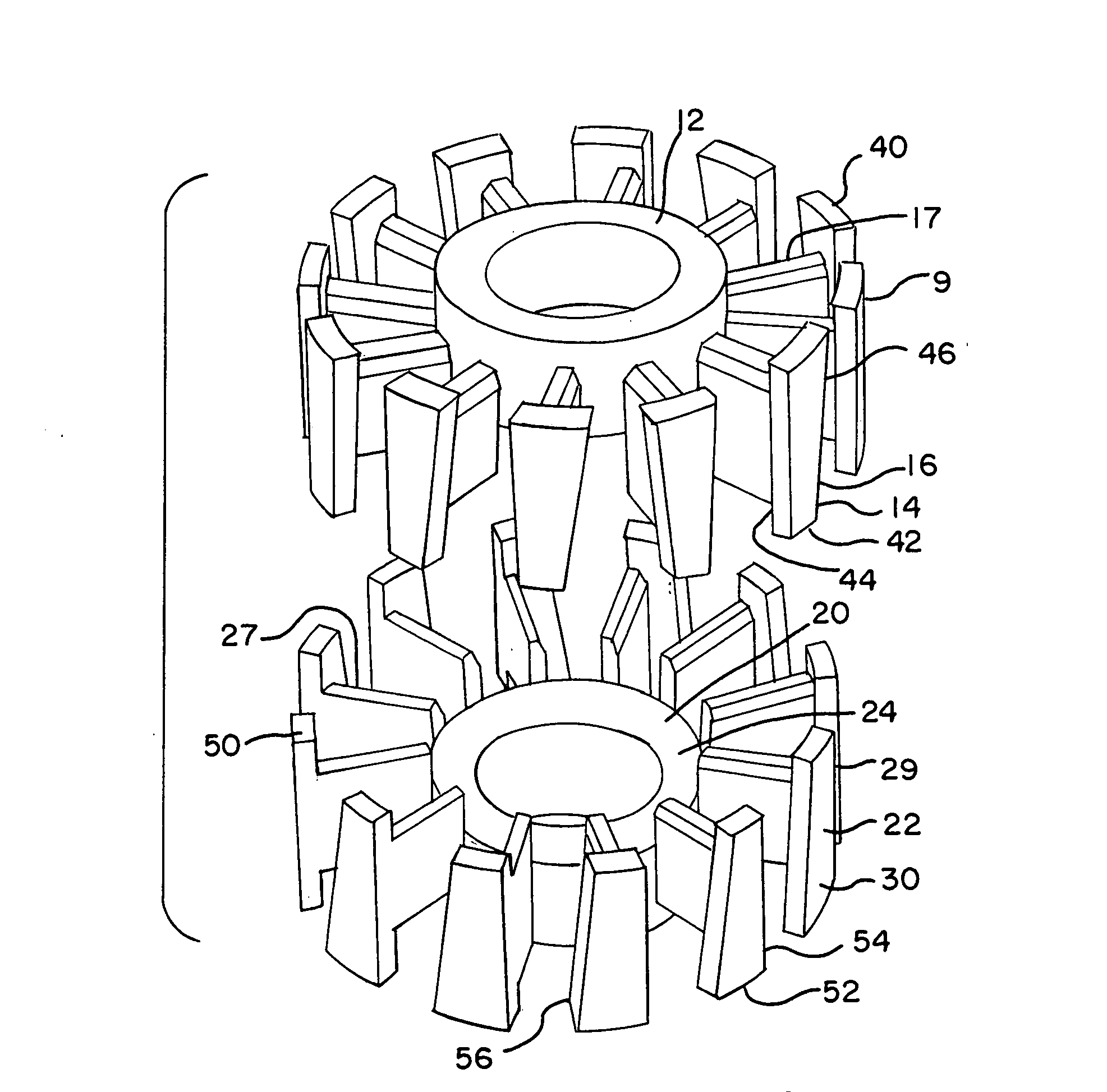
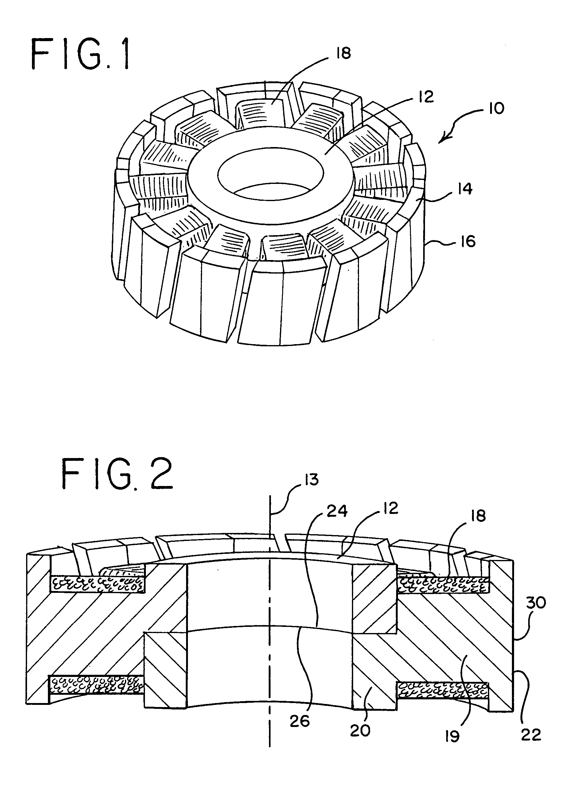
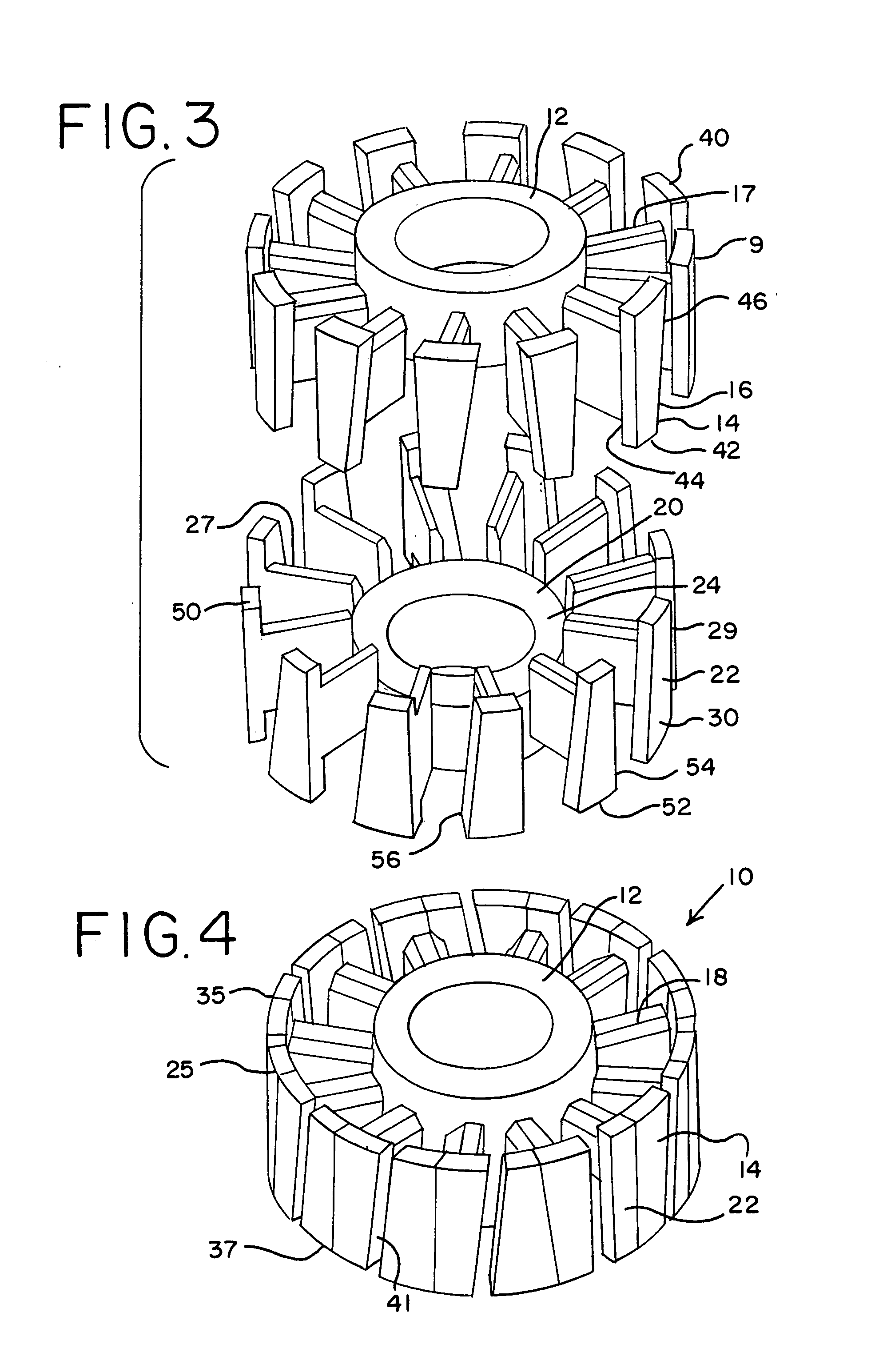
[0019]Referring now to FIGS. 1-4 of the drawings, a component for use in an electrical machine is shown generally at 10. Such component 10 can be a stator or a rotor for use most typically in a motor, but component 10 could also be used in a generator.

[0020]Component 10 is seen to be comprised of a top section 9 and having a center portion 12. Center portion 12 is usually cylindrical in shape with a central open section. Center portion 12 includes a radial center axis 13. A plurality of winding supports 17 extend radially outward from center portion 12 outer surface. The number of each such winding supports can vary based on the size and design of component 10, but the number is usually between eight and twenty-four. Each winding support 17 is generally rectangular in shape, having a top edge and a bottom edge that are parallel and an inside edge adjacent center portion 12 outer surface. Each winding support 17 also has an outer edge.

[0021]Each outer edge of each winding support 17 ...


PUM

PropertyMeasurementUnit
outer angleaaaaaaaaaa
acute angleaaaaaaaaaa
magneticaaaaaaaaaa

Abstract

A compacted magnetic powder metal component assembly for use in an electrical machine is provided. Each component assembly has a top section and a bottom section.Each top section is comprised of a generally cylindrical center portion, a plurality of winding supports extending radially outward from the center portion and a core segment at a radial edge of each winding support.Each bottom section is comprised of a generally cylindrical center portion, a plurality of winding supports extending radially outward from the center portion, and a core segment in a radial edge of each winding segment support.The top section and the bottom section are combined to form the component assembly.

Description

BACKGROUND OF THE INVENTION[0001]The present invention relates to core components for use in electrical machines and, more particularly, a component assembly for use in an electrical machine, most typically an electric motor.[0002]Electrical machines such as motors and generators have a stationary element, usually termed a stator, and movable or rotating elements, typically termed the rotor. The interaction between the stator and the rotor is caused by the interaction of a magnetic field generated by either the stator or the rotor. Such magnetic field is usually generated or induced by electric currents in a winding placed on either the stator or the rotor. Such winding usually comprises a plurality of coils wound about a winding support. The winding support is usually comprised of a soft magnetic material which traditionally is made of laminations of selected steel materials. The laminations are insulated from each other in order to reduce eddy currents.[0003]One concern in the des...

Claims


Application Information

Patent Timeline
Patent Type & Authority Applications(United States)
IPC IPC(8): H02K1/00
CPCH02K1/02H02K1/148Y10T29/49009H02K2201/06H02K1/24H01F3/08
Inventor ENGQUIST, JOHNFARNIA, DAVID
Owner BURGESS NORTON MFG
Learn More