Radio-Frequency Device, And Radio-Frequency Tag Communication Device

a radio frequency device and communication device technology, applied in the direction of burglar alarm mechanical actuation, using reradiation, instruments, etc., can solve the problems of low degree of resolution, inability to accurately achieve the effect of directional detection, and large amount of calculation, etc., to narrow the effective angular range of directivity

Active Publication Date: 2007-12-06
BROTHER KOGYO KK
View PDF4 Cites 66 Cited by
  • Summary
  • Abstract
  • Description
  • Claims
  • Application Information

AI Technical Summary

Benefits of technology

[0060] Preferably, the directivity control portion changes the directivity of transmission of the interrogating wave after a moment of initiation of reception of the reply wave from the radio-frequency tag in response to the interrogating wave, such that a direction of a man lobe of the directivity of transmission is parallel to the predetermined reference direction. In this case, the direction of the main lobe of the directivity of transmission is made coincident with the direction in which the radio-frequency tag to be detected is located, so that the radio-frequency tag can be suitably supplied with an electric energy.
[0061] Preferably, the directivity control portion changes the directivity of transmission of the interrogating wave after a moment of initiation of reception of the reply wave from the radio-frequency tag in response to said interrogating wave, such that a main lobe of the directivity of transmission is substantially coincident with the overlapping area of communications before and after the change of the directivity of transmission. In this case, the direction of the main lobe of the directivity of transmission is made coincident with the direction in which the radio-frequency tag to be detected is located, so that the radio-frequency tag can be suitably supplied with an electric energy.
[0062] Preferably, said directivity control portion changes the directivity of transmission of the interrogating wave such that an area of overlapping of main lobes of the directivity of transmission before and after a change of the directivity of transmission of the unit portion of the interrogating wave is narrowed each time the interrogating wave is transmitted toward the radio frequency tag. In this case, the direction in which the radio-frequency tag exists can be suitably detected, by narrowing the effective angular range of the directivity of communication with the radio-frequency tag.

Problems solved by technology

Although the conventional technique is advantageous for a reduced amount of calculation in a generally known operation of BFA (Beam Forming Antenna) processing for the directional detection, the conventional technique suffers from a drawback of a low degree of resolution and consequent incapability to accurately detect the direction toward the desired communication object in the form of the radio-frequency tag.
However, these techniques undesirably requires complicated processing and a large amount of calculation.
Namely, there has not yet been developed a technique for the directional detection with a high degree of resolution and with a simple processing operation.
Accordingly, the conventional portable radio-frequency tag communication device suffers from instability to maintain its optimum state of communication.
In the directivity control of the array antenna device provided with the plurality of antenna elements described above, it is required to increase the number of the antenna elements, for reducing the width of the main lobe to thereby narrow an effective angular range of the directivity of communication, so that the device undesirably tends to be large-sized.

Method used


Image

  • Radio-Frequency Device, And Radio-Frequency Tag Communication Device
  • Radio-Frequency Device, And Radio-Frequency Tag Communication Device
  • Radio-Frequency Device, And Radio-Frequency Tag Communication Device

Examples


embodiment 1

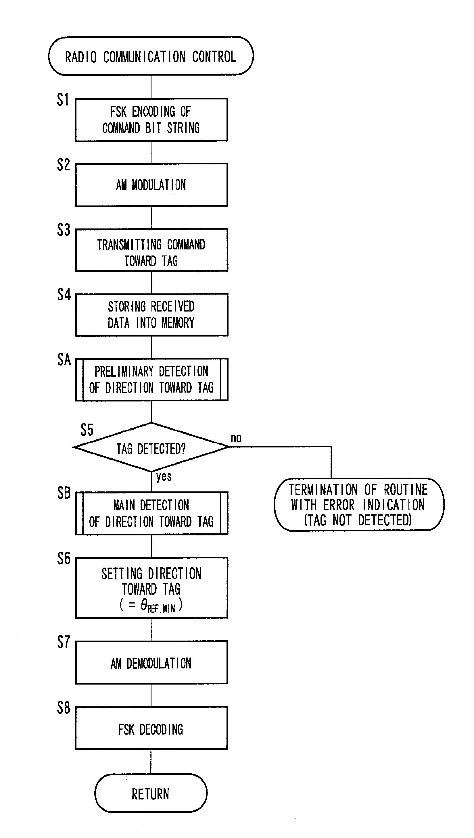
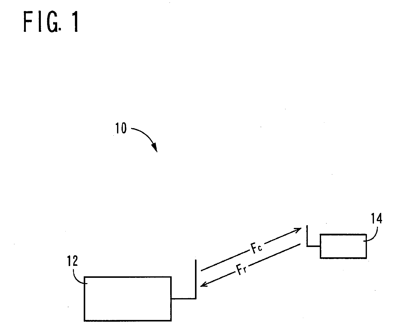
[0132]FIG. 1 is a view for explaining a radio-frequency tag communication system 10 in which a radio-frequency device according to a first aspect of the present invention is suitably used. This radio-frequency tag communication system 10 is a so-called “RFID (Radio-Frequency Identification) system consisting of a radio-frequency tag communication device 12 constructed according to one embodiment of the first aspect of the invention, and at least one radio-frequency tag 14 (one radio-frequency tag in this embodiment each of which is a communication object with which the radio-frequency tag communication device 12 is provided for radio communication. In the RFID system, the radio-frequency tag communication device 12 functions as an interrogator, while the radio-frequency tag 14 functions as a transponder. Described in detail, the radio-frequency tag communication device 12 is arranged to transmit an interrogating wave Fc (transmitted signal) toward the radio-frequency tag 14, and the...

embodiment 2

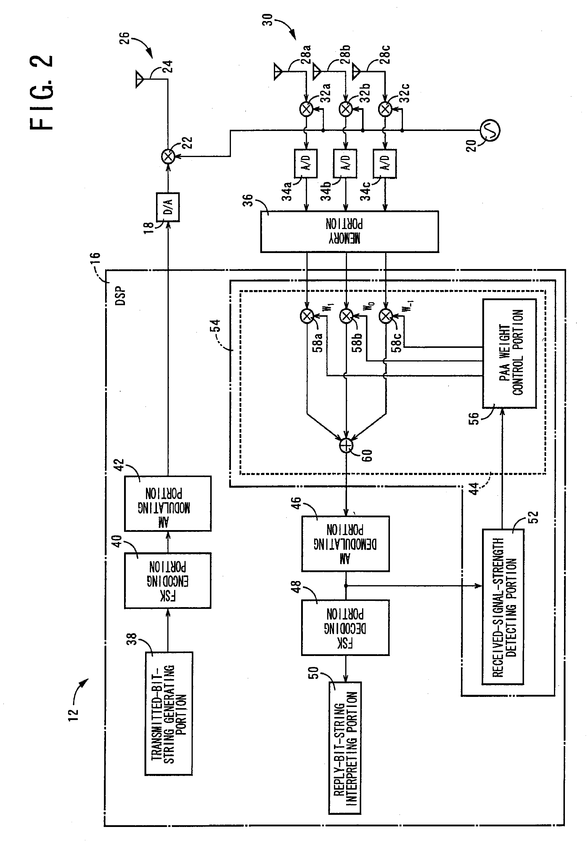
[0155]FIG. 14 is a view for explaining an arrangement of a second embodiment of a radio-frequency tag communication device 80 according to the first aspect of this invention. As shown in FIG. 14, the radio-frequency tag communication device 80 includes: a memory device in the for of a memory portion 82 configured to store the transmitted signal generated by modulation by the AM modulating portion 42, and to apply the transmitted signal to the DSP 16 according to a command from the DSP 16; a plurality of (three in the example of FIG. 14) transmission PAA weight multiplying portions 84a, 84b, 84c (hereinafter collectively referred to as “transmission weight PAA weight multiplying portions 84”, unless otherwise specified) configured to multiply the transmitted signal by PAA weights calculated by the PAA weight control portion 56; a plurality of (three in the example of FIG. 14) transmitted-signal D / A converting portions 18a, 18b, 18c (hereinafter collectively referred to as “transmitte...

embodiment 3

[0172]FIG. 23 is a perspective view showing an appearance of one embodiment of a radio-frequency tag communication device 112 according to a second aspect of this invention. Like the radio-frequency tag communication device 12 in the above-described radio-frequency tag communication system 10 shown in FIG. 1, the radio-frequency tag communication device 112 shown in FIG. 23 is suitably used as an interrogator of the radio-frequency tag communication system 10. The radio-frequency tag communication device 112 includes: a planar display portion (first planar portion) 116 configured to display images relating to radio communication with the radio-frequency tag 14; a planar holder portion (second planar portion) 118 at which the radio-frequency tag communication device 112 is held for carrying; and an operator's control portion 120 having a plurality of operating pushbuttons (switches) disposed on the holder portion 118. The display portion 116 and the holder portion 118 are hinged to e...


PUM


Abstract

A radio-frequency device includes a PAA processing portion configured to control a directivity of reception of a receiver antenna device, a received-signal-strength detecting portion configured to detect a strength of the received signal received by the receiver antenna device, and a direction detecting portion configured to detect the direction toward the communication object, on the basis of a direction in which a higher one of two strength values of the received signal respectively detected in first and second maximum-reception-directivity directions of a predetermined angular difference established by the PAA processing portion is minimal. The direction detecting portion is operated based on a fact that the received signal strength is minimal at the bottom of a gain existing in an area of overlapping of two main lobes extending in the respective two directivity directions of the predetermined angular difference, so that the resolution of detection can be made higher than in the case based on the main lobe direction in which the sensitivity of communication with the radio-frequency tag is maximum. Accordingly, the direction toward the radio-frequency tag can be suitably detected.

Description

[0001] The present application is a Continuation-in-Part of International Application No. PCT / JP2005 / 021644 filed on Nov. 25, 2005, which claims the benefits of Japanese Patent Application Nos. 2004-360030, 2005-74517 and 2005-241519 respectively filed on Dec. 13, 2004, Mar. 16, 2005 and Aug. 23, 2005.BACKGROUND OF THE INVENTION [0002] Field of the Invention [0003] The present invention relates to improvements of a radio-frequency device configured to detect a direction toward a desired communication object, according to a signal received from the communication object, and a radio-frequency tag communication device configured to effect radio communication with radio-frequency tags for writing and reading information on and from the radio-frequency tags. [0004] Description of Related Art [0005] As an example of the radio-frequency device for effecting communication with a desired communication object, there is known an RFID (Radio-Frequency Identification) communication system wherei...

Claims


Application Information

Patent Timeline
Patent Type & Authority Applications(United States)
IPC IPC(8): G08B13/14G01S13/00
CPCH01Q3/04H01Q3/26H04B7/086H04B1/40H01Q19/30
Inventor KURAMOTO, KATSUYUKIOHASHI, TSUYOSHITAKI, KAZUNARI
Owner BROTHER KOGYO KK
Why Eureka
Try Eureka