Light emitting device and method of controlling the same

Inactive Publication Date: 2007-12-06
SAMSUNG ELECTRONICS CO LTD
View PDF35 Cites 6 Cited by
  • Summary
  • Abstract
  • Description
  • Claims
  • Application Information

AI Technical Summary

Benefits of technology

[0015]Exemplary embodiments of the present invention address at least the above problems and/or disadvantages and provide at least the advantages described below. Accordingly, an aspect of the present invention is to provide a light em

Problems solved by technology

In this case, if the switching speed is low, the light emitting unit 22 may not produce a sufficient amount of luminance.
In this case, if the

Method used


Image

  • Light emitting device and method of controlling the same
  • Light emitting device and method of controlling the same
  • Light emitting device and method of controlling the same

Examples


Embodiment Construction

[0034]The matters defined in the description such as a detailed construction and elements are provided to assist in a comprehensive understanding of the embodiments of the invention and are merely exemplary. Accordingly, those of ordinary skill in the art will recognize that various changes and modifications of the embodiments described herein can be made without departing from the scope and spirit of the invention. Also, descriptions of well-known functions and constructions are omitted for clarity and conciseness.

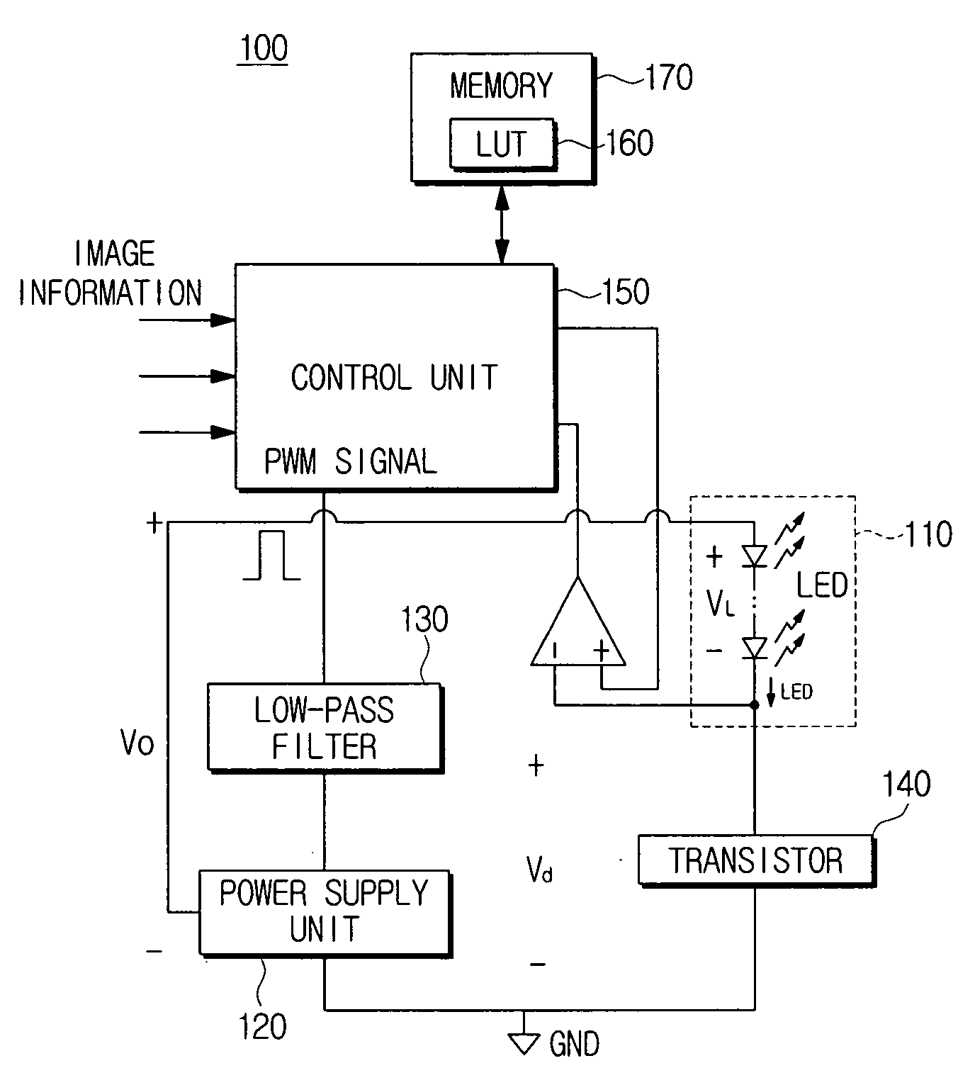
[0035]FIG. 3 is a circuit diagram illustrating the construction of a light emitting device according to an exemplary embodiment of the present invention.

[0036]A light emitting device 100 according to this exemplary embodiment includes a light emitting unit 110, a power supply unit 120, a low-pass filter 130, a transistor 140, a control unit 150, and a memory 170.

[0037]The light emitting unit 110 emits light to a screen (not shown) for displaying an image. The light emitti...


PUM


Abstract

Provided is a light emitting device and a method of controlling the same are disclosed. The light emitting unit includes a power supply unit for supplying a drive voltage to the light emitting unit, and a control unit for comparing a first current level previously applied to the light emitting unit with a second current level to be applied to the light emitting unit in accordance with image information to be displayed using the light emitting unit, and controlling a voltage level applied to the light emitting unit based on a result of comparison.

Description

CROSS-REFERENCE TO RELATED APPLICATION[0001]This application claims the benefit under 35 U.S.C. §119(a) of Korean Patent Application No. 10-2006-049678, filed Jun. 2, 2006, in the Korean Intellectual Property Office, the entire disclosure of which is hereby incorporated by reference.BACKGROUND OF THE INVENTION[0002]1. Field of the Invention[0003]The present invention relates to a light emitting device and a method of controlling the same. More particularly, the present invention relates to a light emitting device and a method of controlling the same, which can optimize a drive voltage to prevent a stress to peripheral devices, without distorting an optical output of a light emitting unit, and thus improve the efficiency of a system.[0004]2. Description of the Related Art[0005]Conventional display devices include direct view cathode ray tubes (CRT), a flat panel displays (FPD) and front and rear projectors. Exemplary FPDs include a liquid crystal display (LCD) panel and a plasma disp...

Claims


Application Information

Patent Timeline
IPC IPC(8): G09G3/36H05B44/00
CPCH05B33/0851H05B33/0815H05B45/10H05B47/165H05B45/325F21Y2115/10
Inventor LEE, SANG-HOONKANG, JEONG-IL
Owner SAMSUNG ELECTRONICS CO LTD
Why Eureka
Try Eureka