Technique for fast activation of a secondary head-end node TE-LSP upon failure of a primary head-end node TE-LSP

Active Publication Date: 2007-12-06
CISCO TECH INC
View PDF27 Cites 141 Cited by
  • Summary
  • Abstract
  • Description
  • Claims
  • Application Information

AI Technical Summary

Benefits of technology

[0029]Advantageously, the novel technique dynamically activates a secondary TE-LPS at a secondary head-end node upon failure of a primary TE-LPS in a computer network. By adjusting BW of the secondary TE-LPS in response to failure of the primary TE-LPS, the novel technique prevents wasting (double-booking) of BW within the network, and allows for minimal delays associated with reserving the desired (primary's) BW amount (e.g., which is faster than auto-BW techniques). In particular, the present invention quickly adjusts the BW of the secondary TE-LPS

Problems solved by technology

Since management of interconnected computer networks can prove burdensome, smaller groups of computer networks may be maintained as routing domains or autonomous systems.
Occasionally, a network element (e.g., a node or link) fails, causing redirection of the traffic that originally traversed the failed network element to other network elements that bypass the failure.
Reconfiguring a network in response to a network element failure using, e.g., pure IP rerouting, can be time consuming.
As such, protection of head-end nodes (and tail-end nodes) may be difficult to accomplish.
Notably, network administrators may recognize that “1 for 1” redundancy attributed to “double booking” (one backup/secondary for each primary) is more expensive than “N for 1” redundancy (one backup/secondary for multiply primaries) that is typically provided by packet switched networks.
While a zero BW TE-LPS provides a redundant TE-LPS, it does not guarantee BW along the TE-LPS,

Method used


Image

  • Technique for fast activation of a secondary head-end node TE-LSP upon failure of a primary head-end node TE-LSP
  • Technique for fast activation of a secondary head-end node TE-LSP upon failure of a primary head-end node TE-LSP
  • Technique for fast activation of a secondary head-end node TE-LSP upon failure of a primary head-end node TE-LSP

Examples


Embodiment Construction

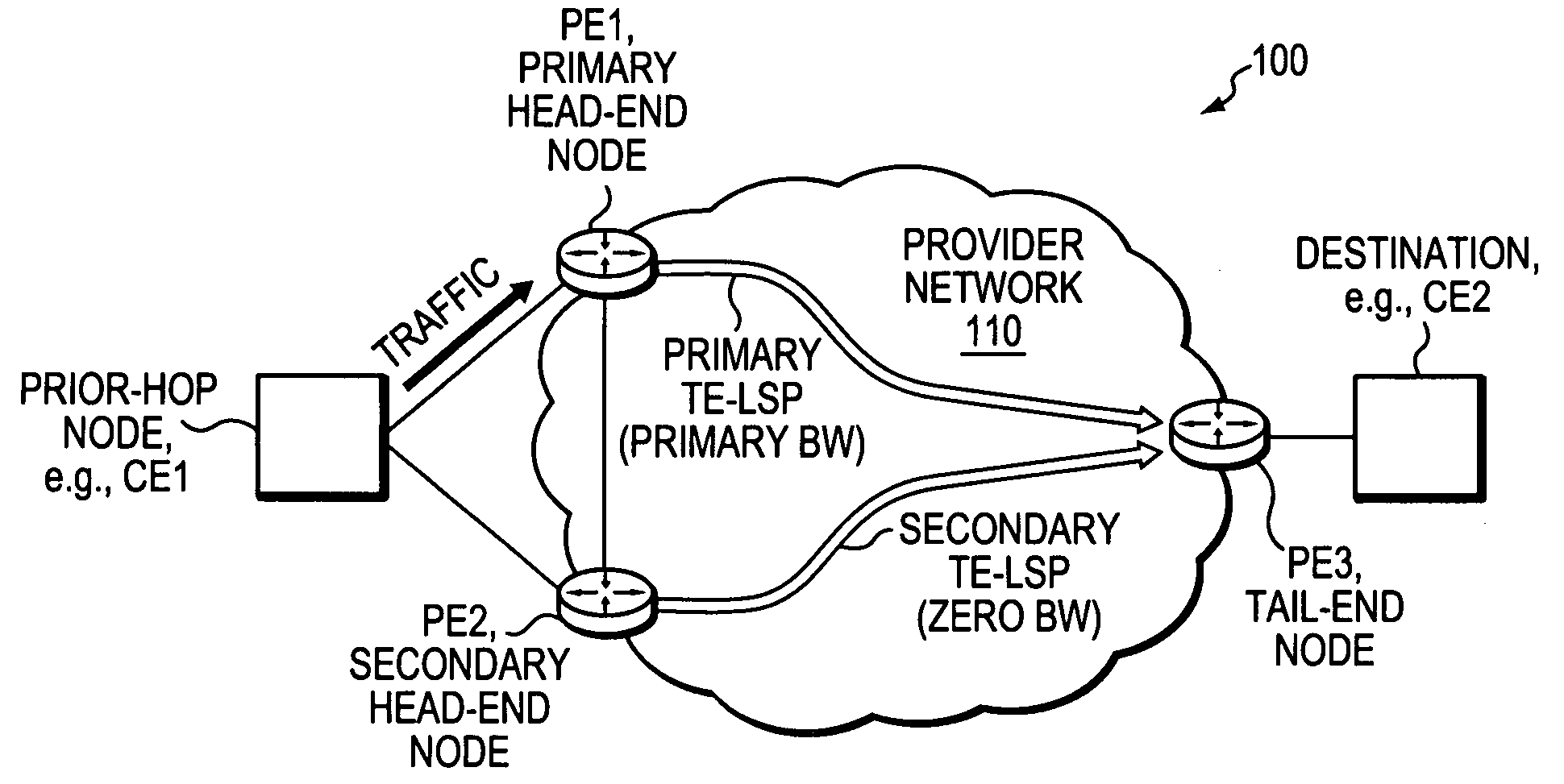
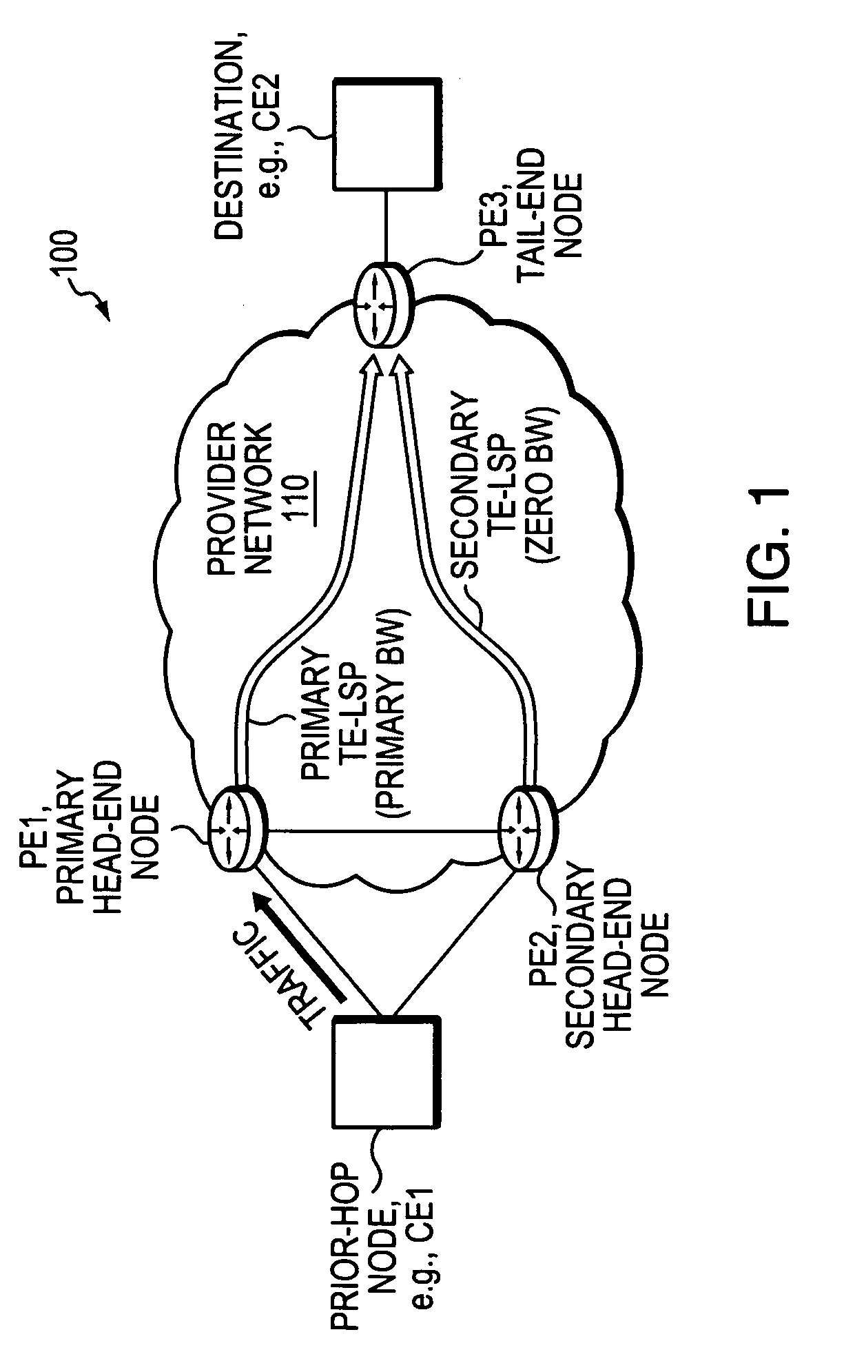
[0037]FIG. 1 is a schematic block diagram of an exemplary computer network 100 illustratively comprising edge devices (provider edge routers) PE1 and PE2 interconnected to PE3 by a provider (core) network 110 (e.g., having one or more links and provider routers, not shown). PE routers PE1 and PE2 may be configured as redundant connections to the provider network 110 for a “prior-hop” node to the PE routers (i.e., one hop prior to the PE routers), such as a customer network edge device (CE1). Example prior-hop routers may include, e.g., Asynchronous Transfer Mode (ATM) switches, media gateways (e.g., for Voice over IP, “VoIP,” Video on Demand, “VoD,” etc.), etc. PE3 may be interconnected to one or more nodes, e.g., destination nodes, such as a CE device CE2. Those skilled in the art will understand that any number of routers and nodes may be used in the computer network, and that the view shown herein is for simplicity. Those skilled in the art will also understand that while the pre...


PUM


Abstract

A technique dynamically activates a secondary Traffic Engineering Label Switched Path (TE-LPs) at a secondary head-end node upon failure of a primary TE-LPs in a computer network. According to the novel technique, a primary head-end node establishes the primary TE-LPs having a primary bandwidth (BW) amount to a primary tail-end node. Also, the secondary head-end node establishes the secondary TE-LPS having zero BW to a secondary tail-end node (e.g., the same as the primary tail-end node). The secondary head-end node monitors the state of the primary TE-LPS, and in response to a failure (e.g., or other state change) substantially immediately adjusts the BW of the secondary TE-LPS to the primary BW amount (“activating” the TE-LPS). A “prior-hop” node to the primary and secondary head-end nodes originally forwarding traffic to the primary head-end node, may then begin forwarding traffic to the secondary head-end node, and thus onto the adjusted secondary TE-LPS.

Description

BACKGROUND OF THE INVENTION[0001]1. Field of the Invention[0002]The present invention relates to computer networks and more particularly to activation of secondary Traffic Engineering Label Switched Path (TE-LPS) upon failure of a primary TE-LPS having separate head-end nodes in a computer network.[0003]2. Background Information[0004]A computer network is a geographically distributed collection of nodes interconnected by communication links and segments for transporting data between end nodes, such as personal computers and workstations. Many types of networks are available, with the types ranging from local area networks (LANs) to wide area networks (WANs). LANs typically connect the nodes over dedicated private communications links located in the same general physical location, such as a building or campus. WANs, on the other hand, typically connect geographically dispersed nodes over long-distance communications links, such as common carrier telephone lines, optical lightpaths, s...

Claims


Application Information

Patent Timeline
IPC IPC(8): H04J3/14
CPCH04J3/14H04L12/5692H04L12/5695H04L41/0663H04L45/00H04L45/22H04L47/825H04L45/302H04L45/50H04L47/728H04L47/746H04L47/822H04L45/28H04L47/70
Inventor VASSEUR, JEAN-PHILIPPEWAINNER, WARREN SCOTT
Owner CISCO TECH INC
Why Eureka
Try Eureka