Laser intra-cavity electronic wavelength tuner

Active Publication Date: 2007-12-06
THE BOEING CO
View PDF8 Cites 56 Cited by
  • Summary
  • Abstract
  • Description
  • Claims
  • Application Information

AI Technical Summary

Problems solved by technology

While this method allows one to tune a laser to a single wavelength or a narrow range of wavelengths, the method is not ideal, because it does not allow the operator to adjust or tune the wavelength once the laser has been built.
The undesired wavelengths are spatially separated and blocked, thereby introducing substanti

Method used


Image

  • Laser intra-cavity electronic wavelength tuner
  • Laser intra-cavity electronic wavelength tuner
  • Laser intra-cavity electronic wavelength tuner

Examples


Embodiment Construction

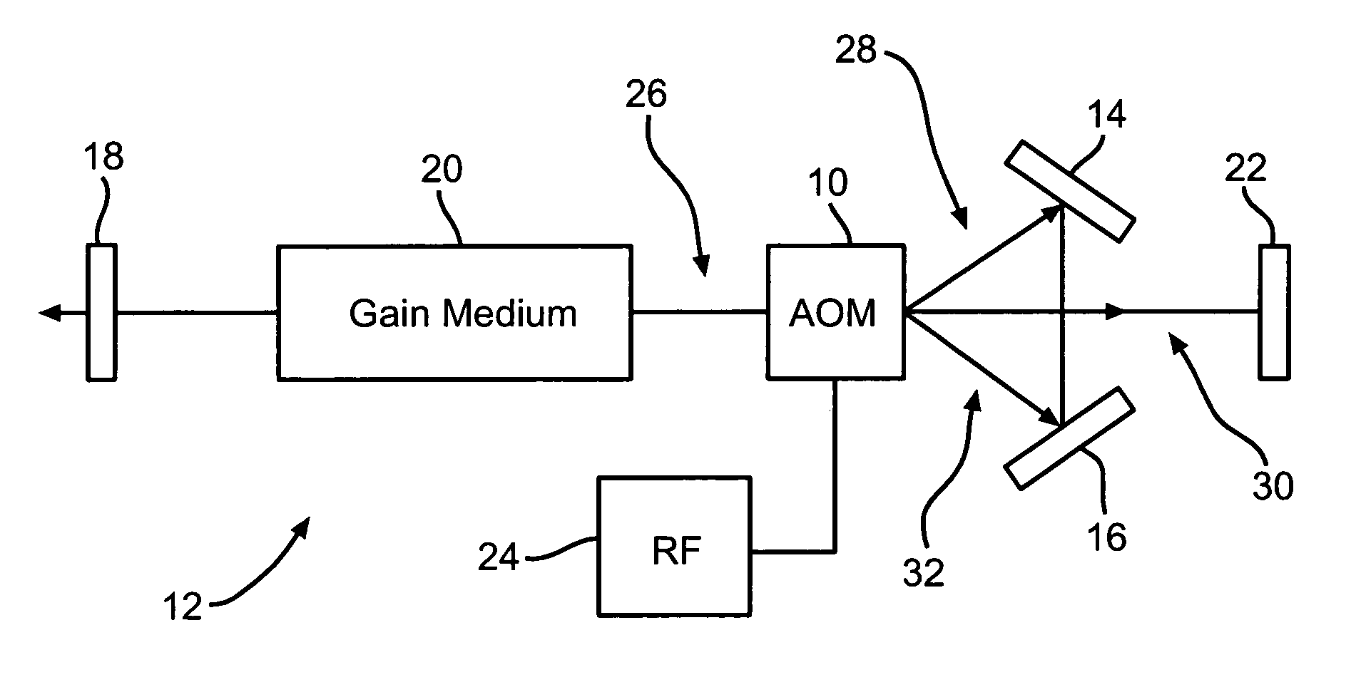
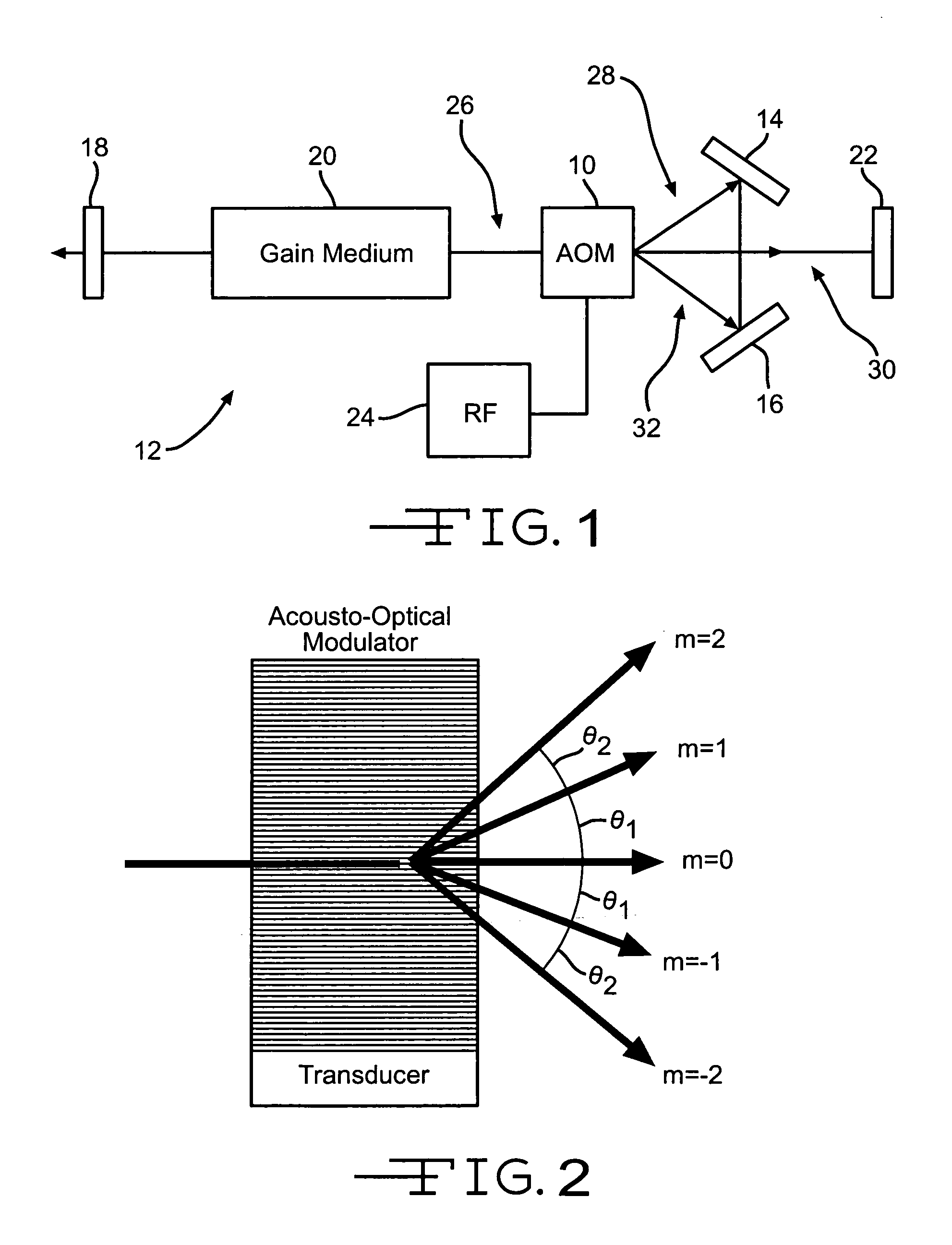
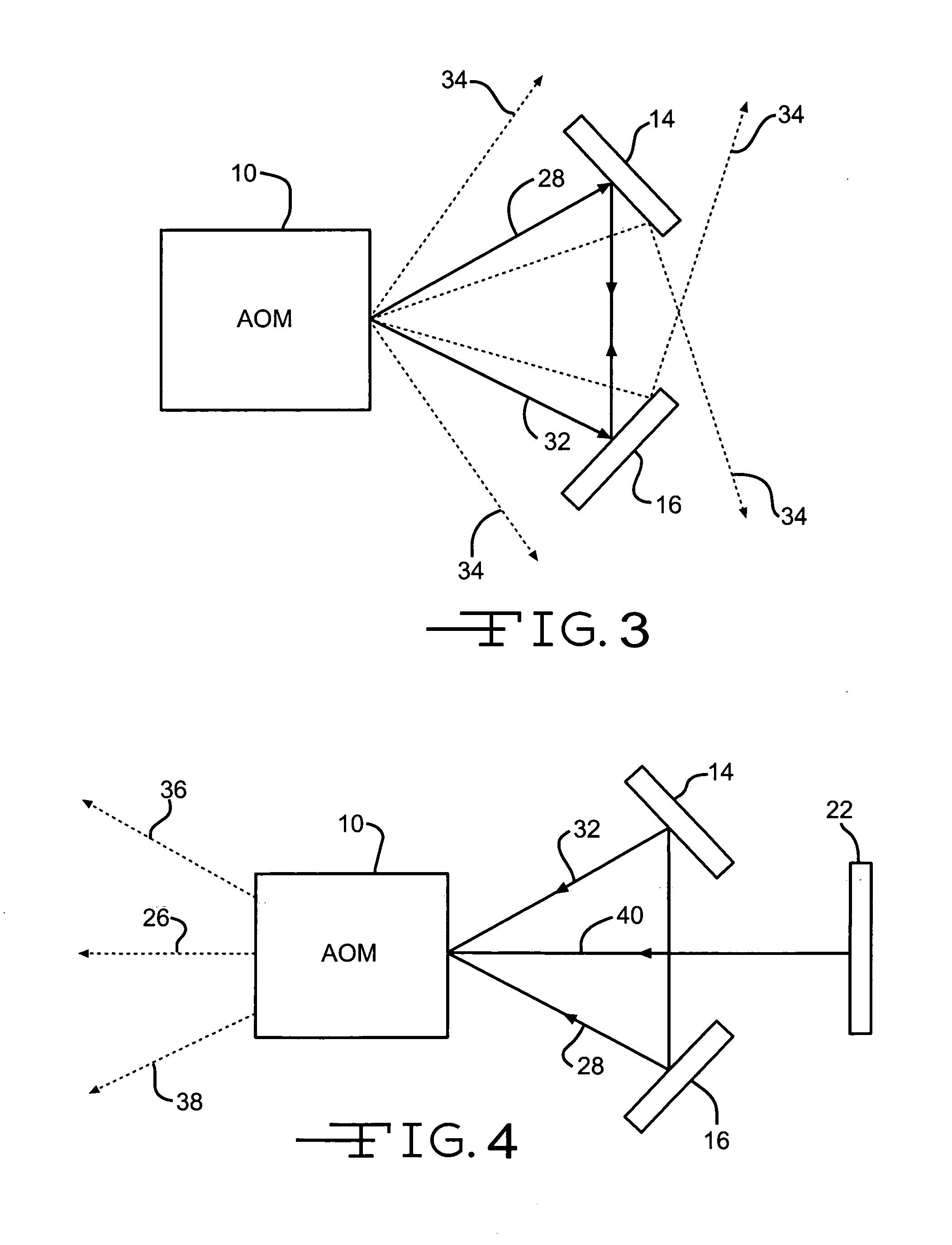
[0012]The present invention, as shown in FIG. 1, uses a single acousto-optical modulator 10 inside a laser cavity 12, along with two additional optical reflectors 14 and 16, to cause the laser cavity 12 to lase at a one of a number of possible wavelengths. The laser cavity 12 consists of a partially-reflecting mirror (or output coupler) 18, a gain medium 20 (such as an Argon-ion gas cell), and a high-reflecting mirror 22. Alternatively, another mirror, such as mirror 22, could act as the output coupler. The type of gain medium is not critical to this invention, and any of a number of common gain media can be used, such as dyes, gas cells, solid state crystals, glass, chemicals, or semiconductors. In the example of an Argon-ion gas cell gain medium, the gain medium can support lasing at a number of different wavelengths: 351 nm, 454.6 nm, 457.9 nm, 465.8 nm, 476.5 nm, 488.0 nm, 496.5 nm, 501.7 nm, 514.5 nm, and 528.7 nm.

[0013]In order to select one desired wavelength and suppress any...


PUM


Abstract

An apparatus for adjusting the wavelength of a laser capable of lasing at multiple wavelengths by using a single acousto-optical modulator and a pair of optical reflectors inside a laser cavity. By adjusting the frequency and amplitude of the radio-frequency source to the acousto-optical modulator, undesired wavelengths are suppressed in the laser cavity, leaving appreciable gain only at the desired wavelength.

Description

BACKGROUND OF THE INVENTION[0001]Many laser gain media are capable of lasing at different wavelengths. By designing a laser cavity in a particular manner, a desired wavelength can be selected from the multiple possible lasing wavelengths by suppressing the gain at undesired wavelengths. Typically, a laser design is fixed for only one wavelength, and once the laser cavity is built, it is not a simple matter to adjust the laser to lase at a different wavelength.[0002]For example, a simple method for selecting a particular wavelength is to use mirrors that only efficiently reflect the desired wavelength. For instance, dielectrically coated mirrors can be used that reflect only a narrow range of wavelengths. While this method allows one to tune a laser to a single wavelength or a narrow range of wavelengths, the method is not ideal, because it does not allow the operator to adjust or tune the wavelength once the laser has been built. In order to change the operating wavelength of the la...

Claims


Application Information

Patent Timeline
IPC IPC(8): H01S3/10
CPCH01S3/0816H01S3/2207H01S3/1068H01S3/082
Inventor MUENTER, STEVEN E.SEIDEN, HAROLD N.
Owner THE BOEING CO
Why Eureka
Try Eureka