

Scanning slot cone-beam computed tomography and scanning focus spot cone-beam computed tomography
- Summary
- Abstract
- Description
- Claims
- Application Information
AI Technical Summary
Benefits of technology
Problems solved by technology
Method used
Image

Examples
Embodiment Construction
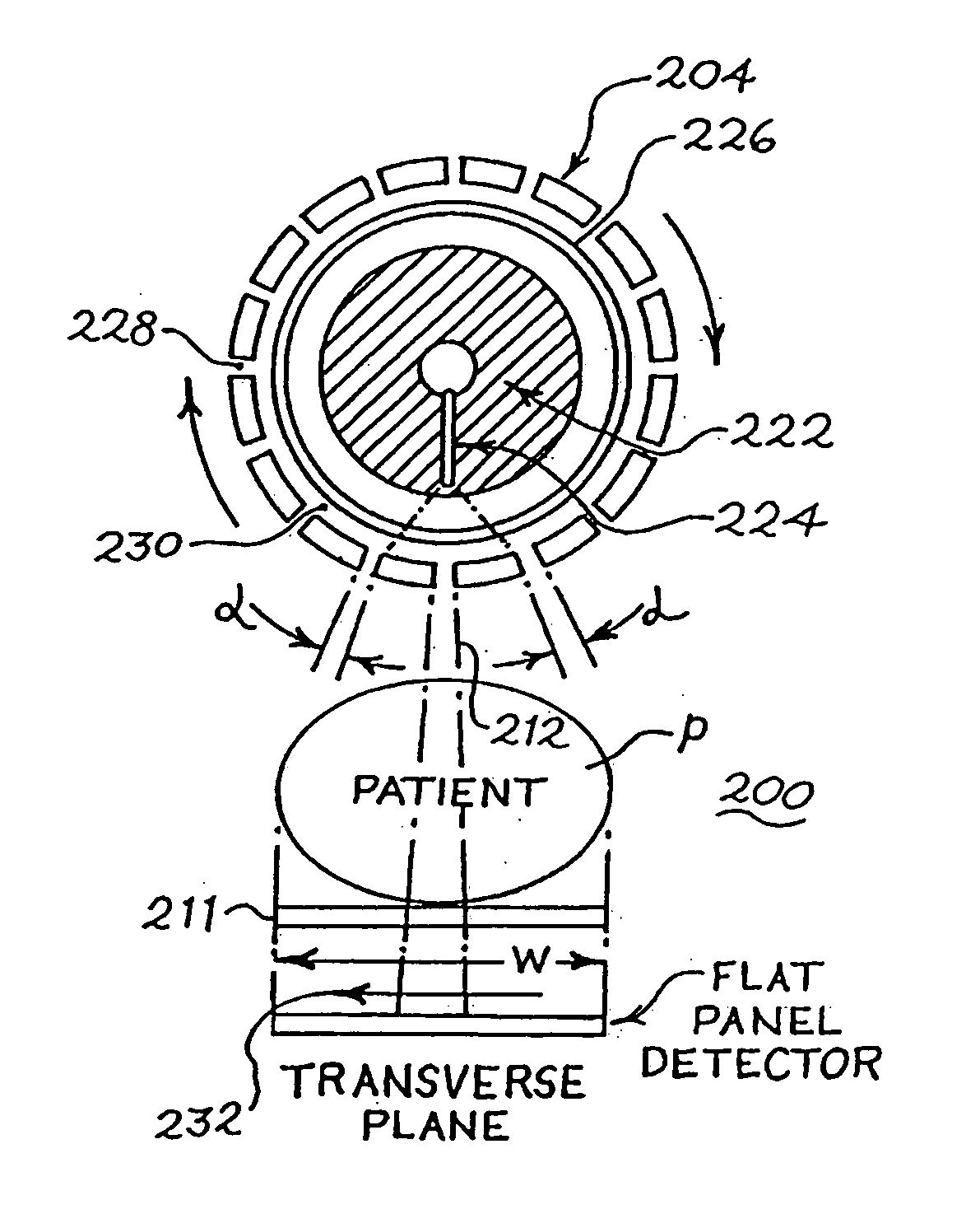
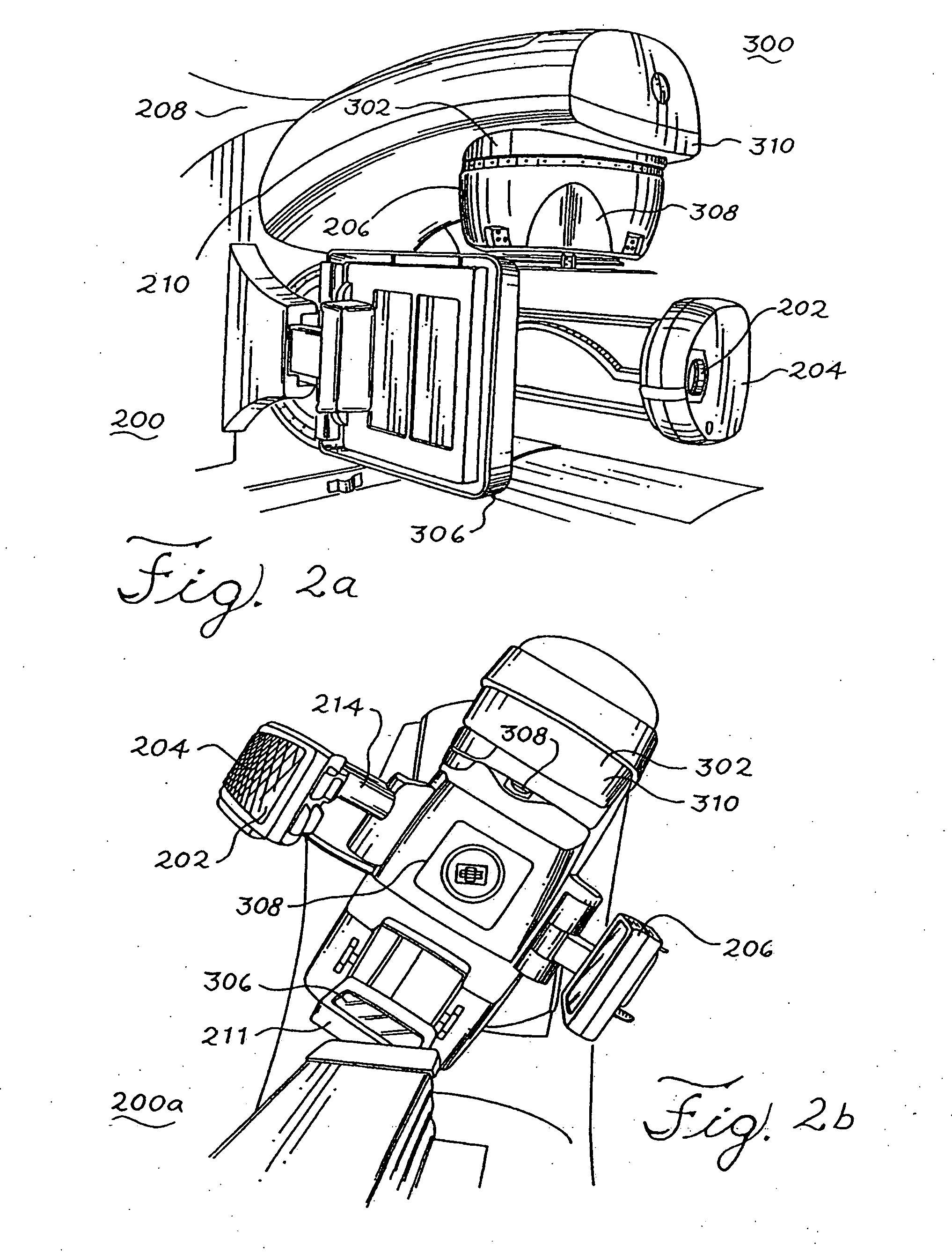
[0057] Referring now to FIGS. 2-16, various imaging systems embodying the principles of the present invention are illustrated, wherein like elements are denoted by like numerals. In particular, FIG. 2a shows an embodiment of a wall-mounted scanning slot cone-beam computed tomography system 200 and megavoltage portal imaging system 300 that can be adapted to be used with the cone-beam computed tomography and megavoltage portal imaging system sold under the tradename Synergy by Elekta of Crawley, the United Kingdom. The system 200 may be retrofitted onto an existing or new radiation therapy system that includes a separate radiation therapy x-ray source. The cone-beam computed tomography system 200 includes an x-ray source, such as x-ray tube 202, a rotary collimator 204 and a flat-panel imager / detector 206 mounted on a gantry 208.
[0058] As shown in FIG. 2a, the flat-panel imager 206 can be mounted to the face of a flat, circular, rotatable drum 210 of the gantry 208 of a medical line...
PUM
 Abstract
Description
Claims
Application Information