Doll Joint

a doll and joint technology, applied in the field of doll joints, can solve the problems of compromising the lifelike effect of the doll, the doll cannot have a lifelike appearance, and the position cannot be maintained without assistan

Inactive Publication Date: 2007-12-06
HIMSTEDT ANNETTE
View PDF11 Cites 12 Cited by
  • Summary
  • Abstract
  • Description
  • Claims
  • Application Information

AI Technical Summary

Benefits of technology

[0006] Therefore, the object of the present invention is, on the one hand, to bring the movable elements of the doll permanently into a desired position that is as lifelike as possible, and, on the other hand, to ensure a lifelike effect when the doll is taken hold of. In addition, individual parts of the doll's arm or of the doll's leg should be able to be moved. Moreover, the useful life of the joints and their ability to withstand stresses are also to be improved, and assembly is to be made simpler. Manufacturing costs are also to be reduced. Solution
[0008] The rotary element and the respective end area of the doll's arm part or doll's leg part and the additional element inserted into the doll's arm part or doll's leg part are in this case designed in such a way that, in the position of use, they form a kind of ball, as is also present in the human body. This permits a better positioning of the movable elements, similarly to the human body. Moreover, because of this design, the doll also acts in a lifelike manner when taken hold of, since the user's fingers do not press into the textile sleeve in this area of the doll, as was hitherto the case, and come up against the joint made from metal or the like.
[0012] The rotary element is moreover assigned a holding element which is inserted into a correspondingly shaped recess in the doll's body or in the doll's arm part or doll's leg part. A constriction in the recess engages behind the holding element and secures the latter, and thus also the rotary element, in the recess, as a result of which it is possible to prevent the whole joint connection from slipping out.
[0013] The spherical element is also assigned a holding element which is inserted into a recess provided for it in the doll's arm part or doll's leg part and is secured there by means of a constriction. Release of the spherical element from its connection to the doll's arm part or doll's leg part is thus avoided.
[0020] With the present joint, it is possible, for example, to turn a doll's arms or doll's legs in any imaginable direction, without the doll losing any of its lifelike quality when looked at or when taken hold of.

Problems solved by technology

Although this allows each limb of a doll to be brought into a lifelike position, this position cannot be maintained without assistance.
As before, however, the doll does not have a lifelike appearance, on the one hand because the joint is covered by a textile sleeve.
On the other hand, the lifelike effect of the doll is compromised by the fact that, when the doll is taken hold of at the joint, an impression is formed in the textile sleeve, since the latter is not designed to be shape-stable, but instead serves only for covering the joint.
Moreover, it has hitherto not been possible to move or rotate individual parts, for example of a doll's arm or of a doll's leg.

Method used


Image

  • Doll Joint
  • Doll Joint
  • Doll Joint

Examples


Embodiment Construction

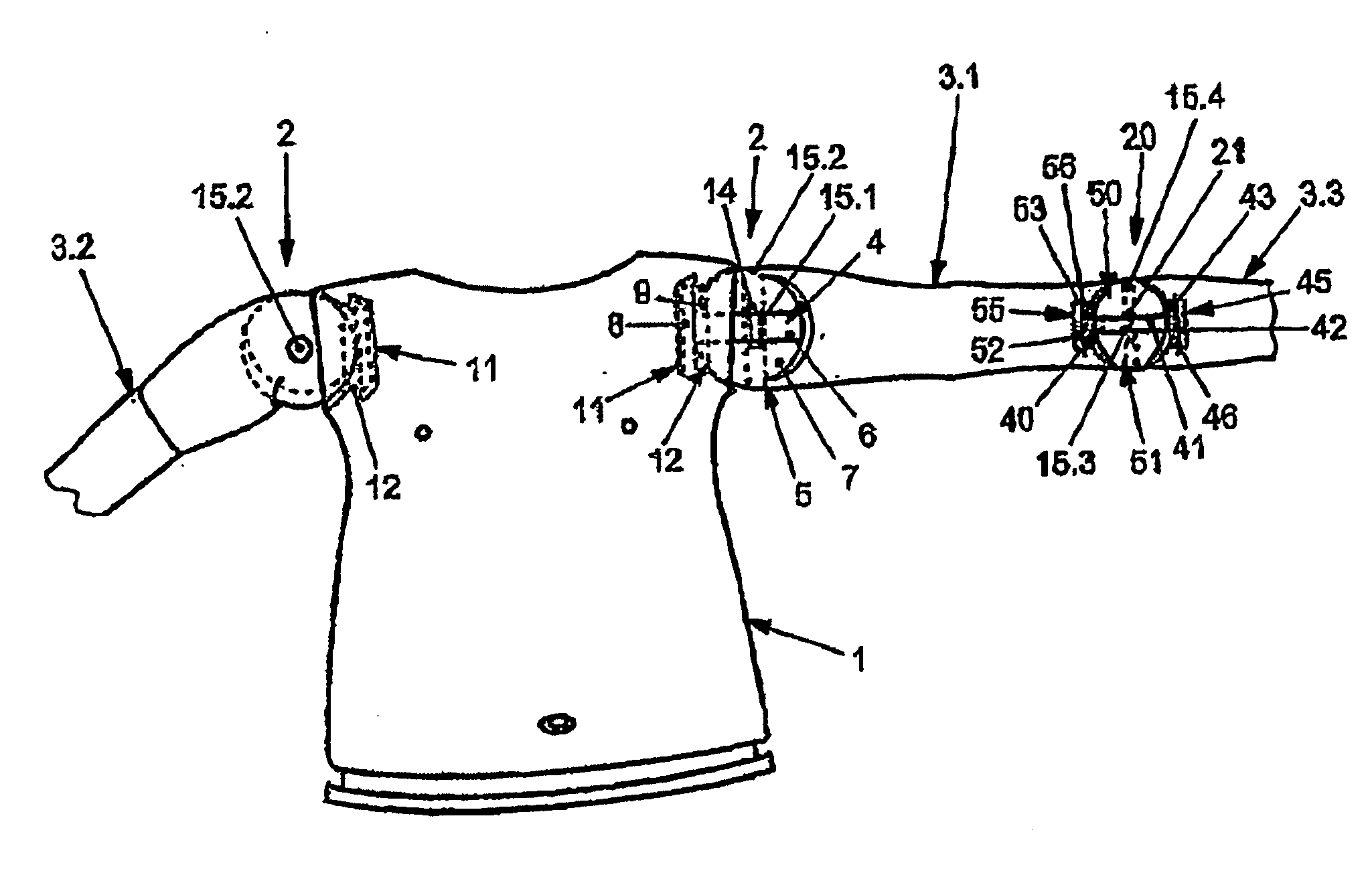
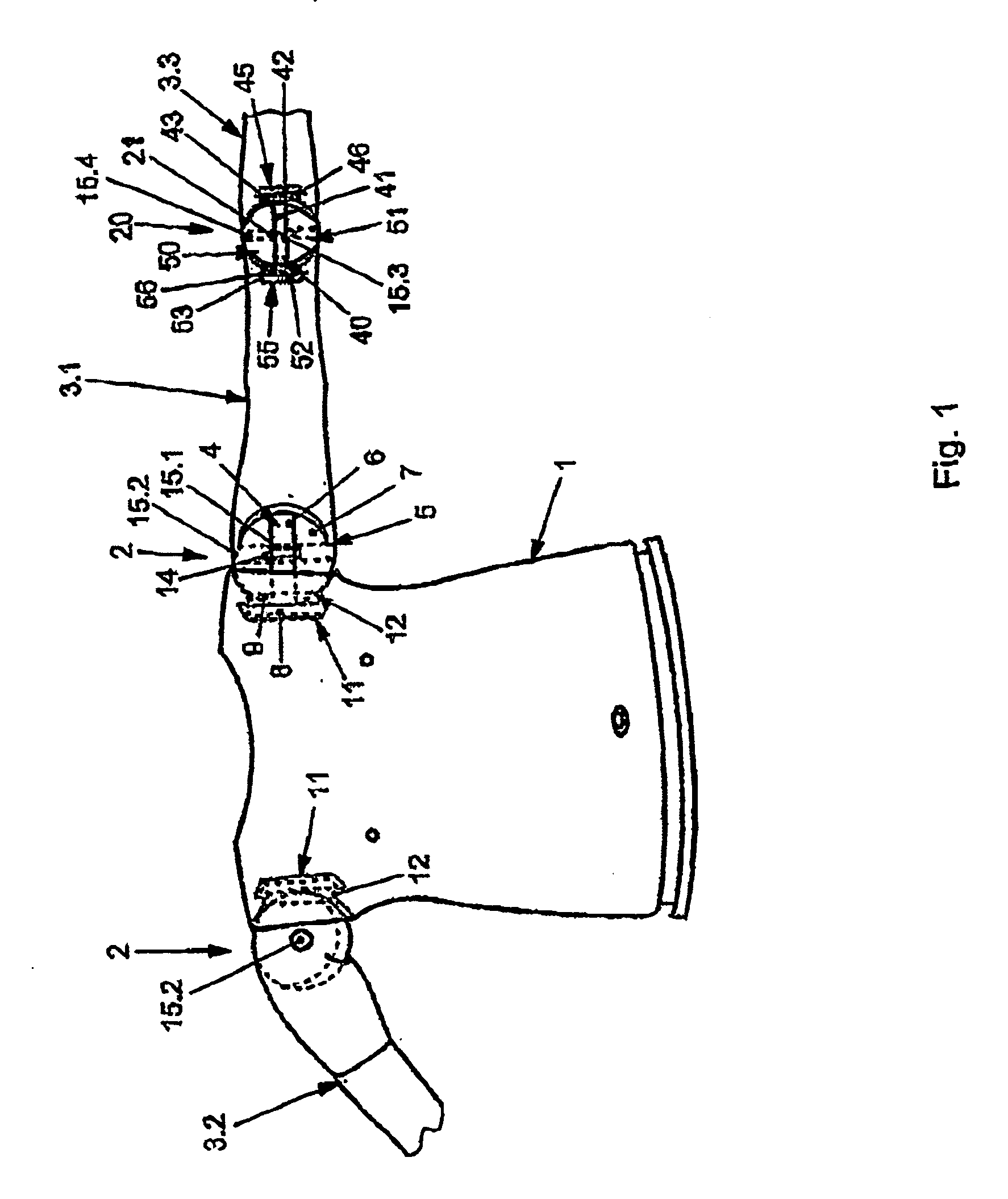
[0035]FIG. 1 depicts the upper region of a doll's body 1 to which a doll's arm part 3.1 or 3.2 is secured via a respective joint 2. At the other end, a further doll's arm part 3.3 is secured on the doll's arm part 3.1 via a further joint 20.

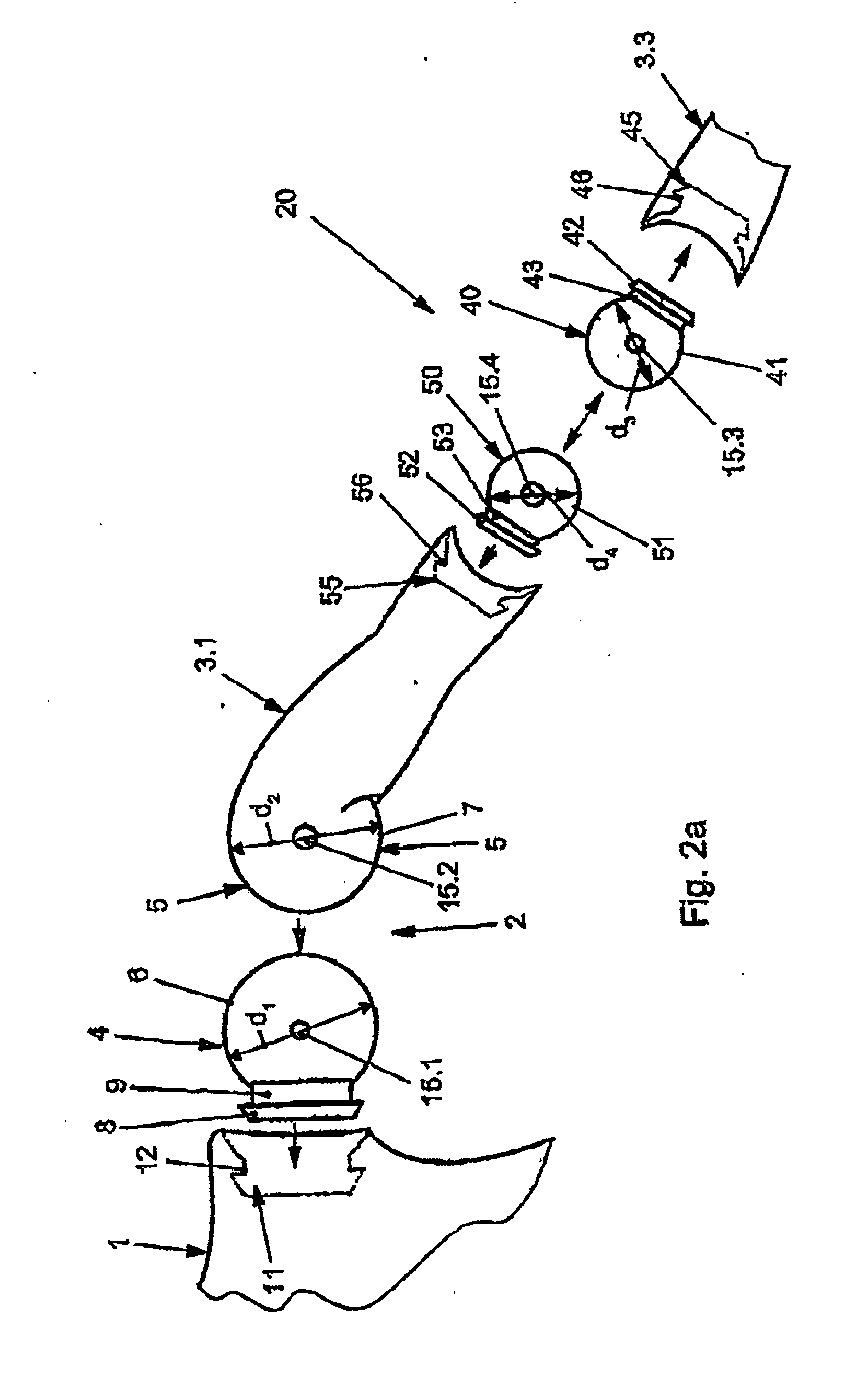
[0036] The joints 2 and 20 are composed, as shown in FIGS. 2a and 2b, of a rotary element 4, 40, preferably in the form of a disk, and of a spherical end area 5 of the doll's arm part 3.1 itself or a spherical element 50. A diameter d1, d3 of the rotary element 4, 40, respectively, corresponds to a diameter d2, d4 of the spherical end area 5 of the doll's arm part 3.1 and the spherical element 50, so that outer faces 6, 7 of the rotary element 4 and of the spherical end area 5 or outer faces 41, 51 of the rotary element 40 or of the spherical end 50 lie almost in one plane in the position of use and rest flush on one another.

[0037] The rotary element 4, 40 is also assigned a holding element 8, 42, respectively, which is assigned a guide 9, 43, ...


PUM


Abstract

A joint for fixing movable elements to a doll's torso or for interconnecting individual elements, especially a doll's arm sections and / or leg sections. A rotating element is rotatably inserted into the doll's torso and / or into one element and / or into another element while a final area (5,500) of said element or an element that is inserted thereinto is rotatably connected to said rotating element.

Description

[0001] The invention relates to a joint for securing movable elements to a doll's body or for connecting individual elements, in particular doll's arm parts and / or doll's leg parts, to one another. PRIOR ART [0002] Dolls of many shapes and designs are known. The present document is concerned primarily with extremely high-quality dolls which are extremely valuable not only because of their design, but also because of the material used. These dolls are intended to be as lifelike as possible, some of them being of a size corresponding to actual life size. Each type of doll is manufactured only in a small number and is in most cases made of a special plastic imitating the body, for example a vinyl. They are cast in special molds. To connect the individual movable elements, such as the head, arms and legs, joints are known, such as the ones that are described in DE 4037962 or DE 29602347. [0003] DE 40 37 962 describes a connecting piece composed of a textile material which is filled with...

Claims


Application Information

Patent Timeline
Patent Type & Authority Applications(United States)
IPC IPC(8): A63H3/46
CPCA63H3/46
Inventor HIMSTEDT, ANNETTE
Owner HIMSTEDT ANNETTE
Why Eureka
Try Eureka