Radio communication method, transmitter, and receiver

a radio communication and receiver technology, applied in the field of radio communication methods, a transmitter and a receiver, can solve the problems of difficult to ensure robust transmission capacity, poor condition of antennas, and significant long time of searching for optimal antennas, and achieve the effect of small operation

Inactive Publication Date: 2007-12-06
FUJITSU LTD
View PDF4 Cites 109 Cited by
  • Summary
  • Abstract
  • Description
  • Claims
  • Application Information

AI Technical Summary

Benefits of technology

[0015] With the foregoing problems in view, it is an object of the present invention to make it possible to select the optimal transmission antennas and reception antennas in accordance with radio environment with high speed with a smaller amount of operation than the previous art.

Problems solved by technology

In addition, according to the art of the patent document 2, a greater number of antennas of the BS will result in a significantly long time of searching the optimal antenna.
Thus, the condition of antennas is sometimes not good depending upon communication environment, and it is difficult to ensure robust transfer capacity.
In addition, in a case where the number of antennas of the RS is large, if all the antennas of the BS end and of the RS end are used at the same time, costs and complexity are increased.
Further, when antenna selection is performed between the BS and the RS, it takes a significant length of time to look for the optimum antennas because of the great of number of antennas.

Method used


Image

  • Radio communication method, transmitter, and receiver
  • Radio communication method, transmitter, and receiver
  • Radio communication method, transmitter, and receiver

Examples


first embodiment

[A] First Embodiment

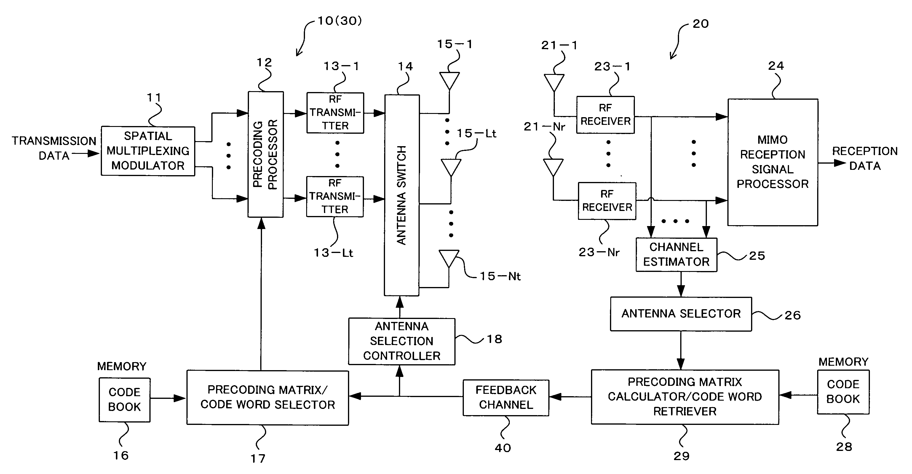
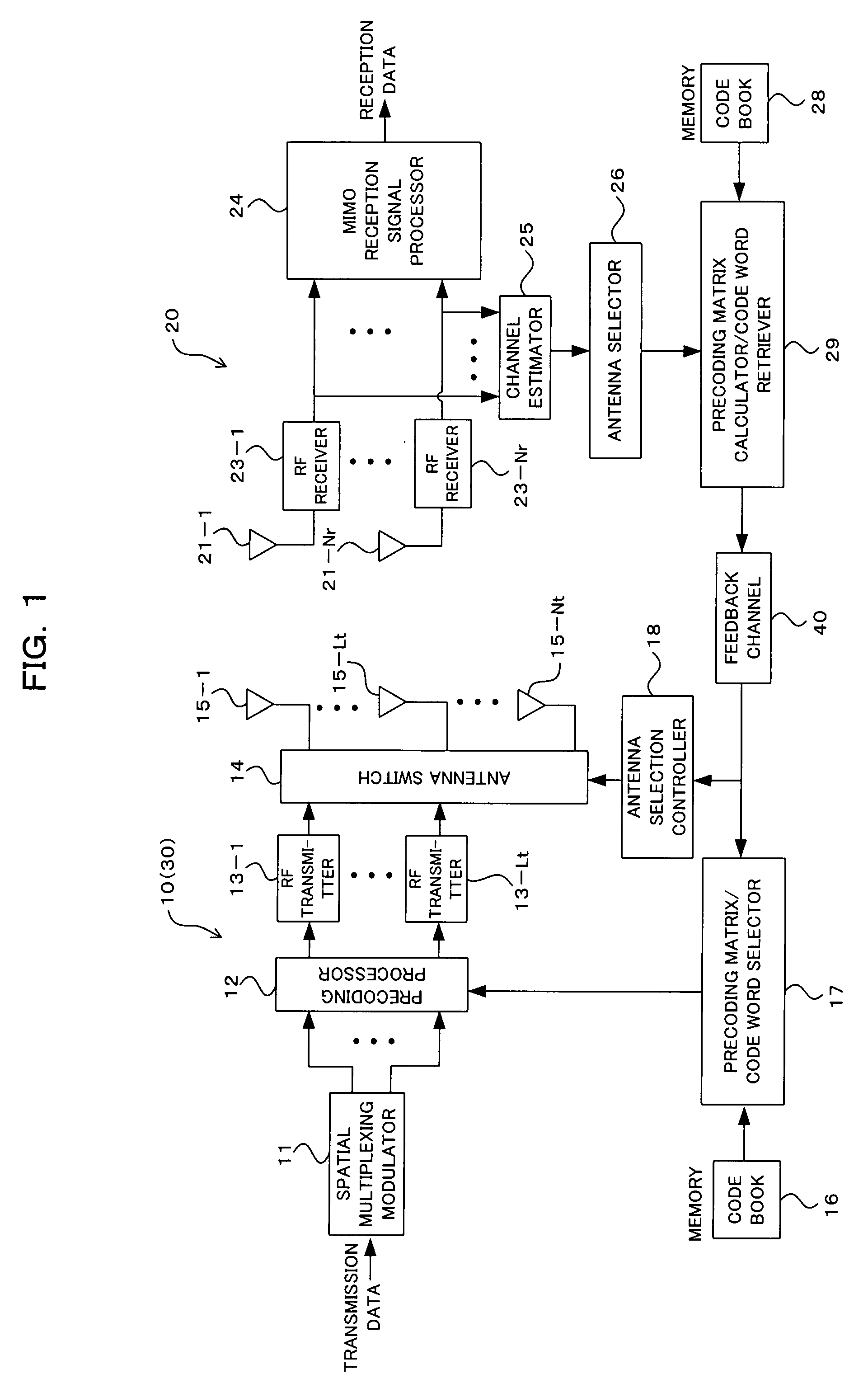
[0041]FIG. 1 is a diagram showing a construction of a multi antenna radio communication system according to a first embodiment of the present invention. The radio communication system of FIG. 1 includes at least one base station apparatus (BS) 10 as a transmitter, and at least one mobile station apparatus (MS) 20 as a receiver. An important part of the BS 10 includes a spatial multiplexing modulator 11, a precoding processor 12, Lt-number (Lt is a integer greater than 1) of RF transmitter 13-1 through 13-Lt (hereinafter will be described as an RF transmitter 13 when individuals are not distinguished), an antenna switch 14, Nt-number (Nt is an integer greater than 1, and Nt≧Lt) of transmission antennas 15-1 through 15-Nt (hereinafter will be described as transmission antenna 15 when individuals are not distinguished), a code book memory 16, a precoding matrix / code word selector 17, and a transmission antenna selection controller 18.

[0042] On the other hand, an im...

second embodiment

[B] Second Embodiment

[0126]FIG. 6 is a block diagram showing a construction of multi antenna radio communication system according to second embodiment of the present invention. The radio communication system of FIG. 6 includes at least one base station (BS) 10 and at least one relay station (RS) apparatus 30. The BS 10 is constructed as in that of the first embodiment; the important part of the RS 30 includes Nr-number (Nr is an integer greater than 1) of reception antennas 31-1 through 31-Nr (hereinafter described as reception antenna 31 when distinction is not made), an antenna switch 32, Lr-number (Lr is an integer greater than 1 and Lr≦Nr) of RF receiver 33-1 through 33-Lr (hereinafter described as an RF receiver 33 when distinction is not made),

a MIMO reception signal processor 34, a channel estimator 35, an antenna selector (to-be-used antenna selector) 36, an antenna section controller 37, a code book memory 38, and a precoding matrix calculator / code word retriever 39.

[012...


PUM


Abstract

Of the antenna group composed of multiple ones of the transmission antennas and multiple ones of the reception antennas, the present method selects an antenna group which satisfies a first criterion relating to communication quality. Out of combinations of transmission antennas and reception antennas included in the selected antenna group, combinations which satisfy a second criterion relating to communication quality are selected. Using a part of or all of the selected combinations of transmission antennas and reception antennas, the above-mentioned communication is performed. As a result, selection of optimal transmission antennas and reception antennas according to radio communication environment can be performed with high speed with a smaller amount of operation amount than the previous art.

Description

CROSS REFERENCE TO RELATED APPLICATION(S) [0001] This application is based on and hereby claims priority to Japanese Application No. 2006-273018 filed on Oct. 4, 2006 in Japan, the contents of which are hereby incorporated by reference. BACKGROUND OF THE INVENTION [0002] (1) Field of the Invention [0003] The present invention relates to a radio communication method, a transmitter, and a receiver. For example, the present invention relates to an art suitable for use in selecting transmission antennas and reception antennas in a radio communication system using MIMO (Multiple Input Multiple Output). [0004] (2) Description of the Related Art [0005] Recently, MIMO (Multiple-Input Multiple-Output) becomes a focus of attention as an art which makes possible a great amount (high speed) of data communication effectively using frequency bands. MIMO is an art for improving the transmission rate, without necessity of enlarging frequency bands, by means of using multiple antennas both in transm...

Claims


Application Information

Patent Timeline
Patent Type & Authority Applications(United States)
IPC IPC(8): H04B1/02H04B7/08H04B1/06H04J99/00
CPCH04B7/0417H04B7/043H04B7/061H04B7/0874H04B7/0639H04B7/0691H04B7/0634H04B7/0689H04B7/0697
Inventor TAKANO, TAKESHIZHOU, LIANG
Owner FUJITSU LTD
Why Eureka
Try Eureka