

Medical guide wire
a technology of guide wires and wires, applied in the field can solve the problems of low steering ability of medical guide wires b>110/b>, no known structure of guide wire tips can penetrate successfully, and achieve the effect of high steering ability
- Summary
- Abstract
- Description
- Claims
- Application Information
AI Technical Summary
Benefits of technology
Problems solved by technology
Method used
Image

Examples
first embodiment
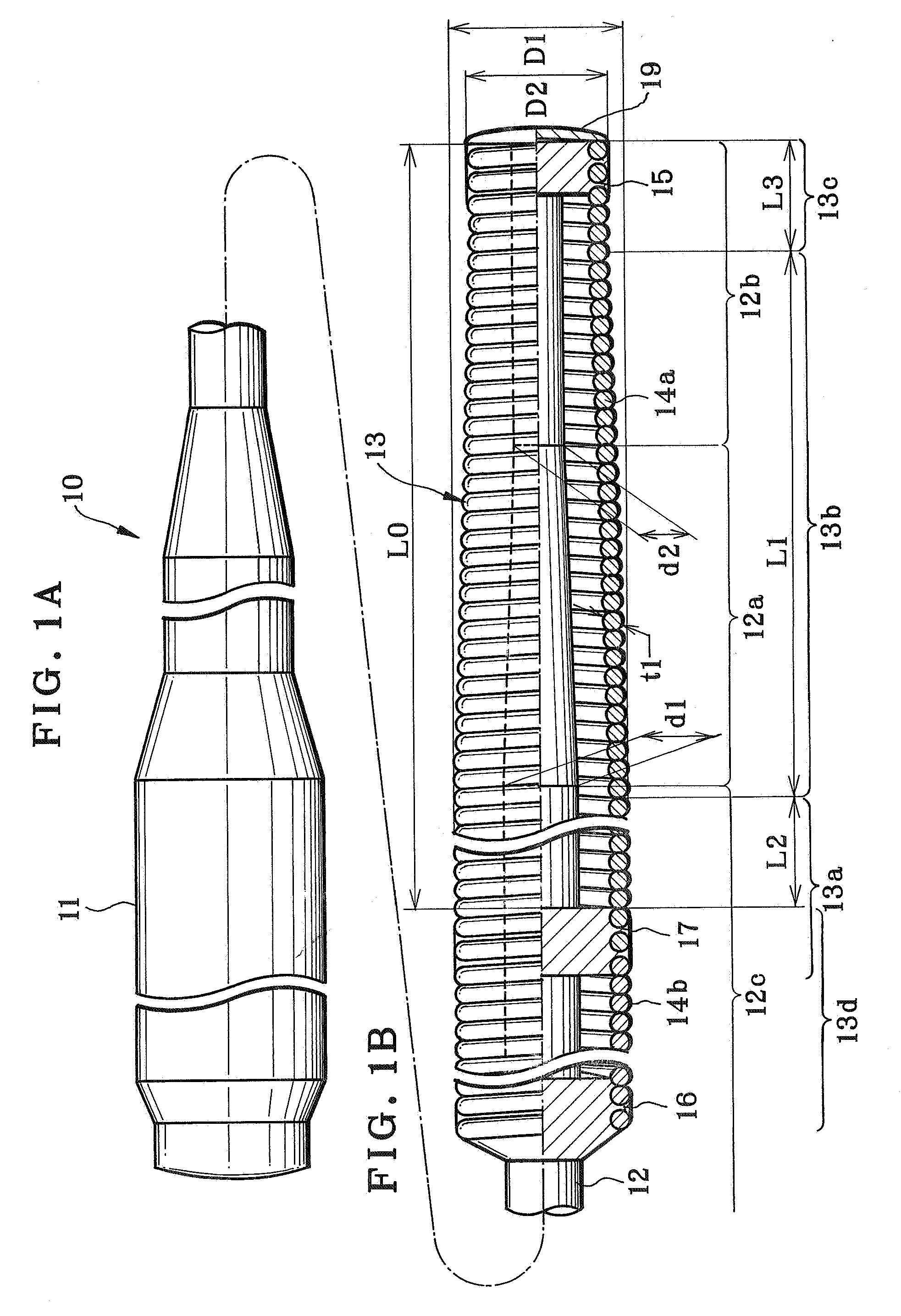
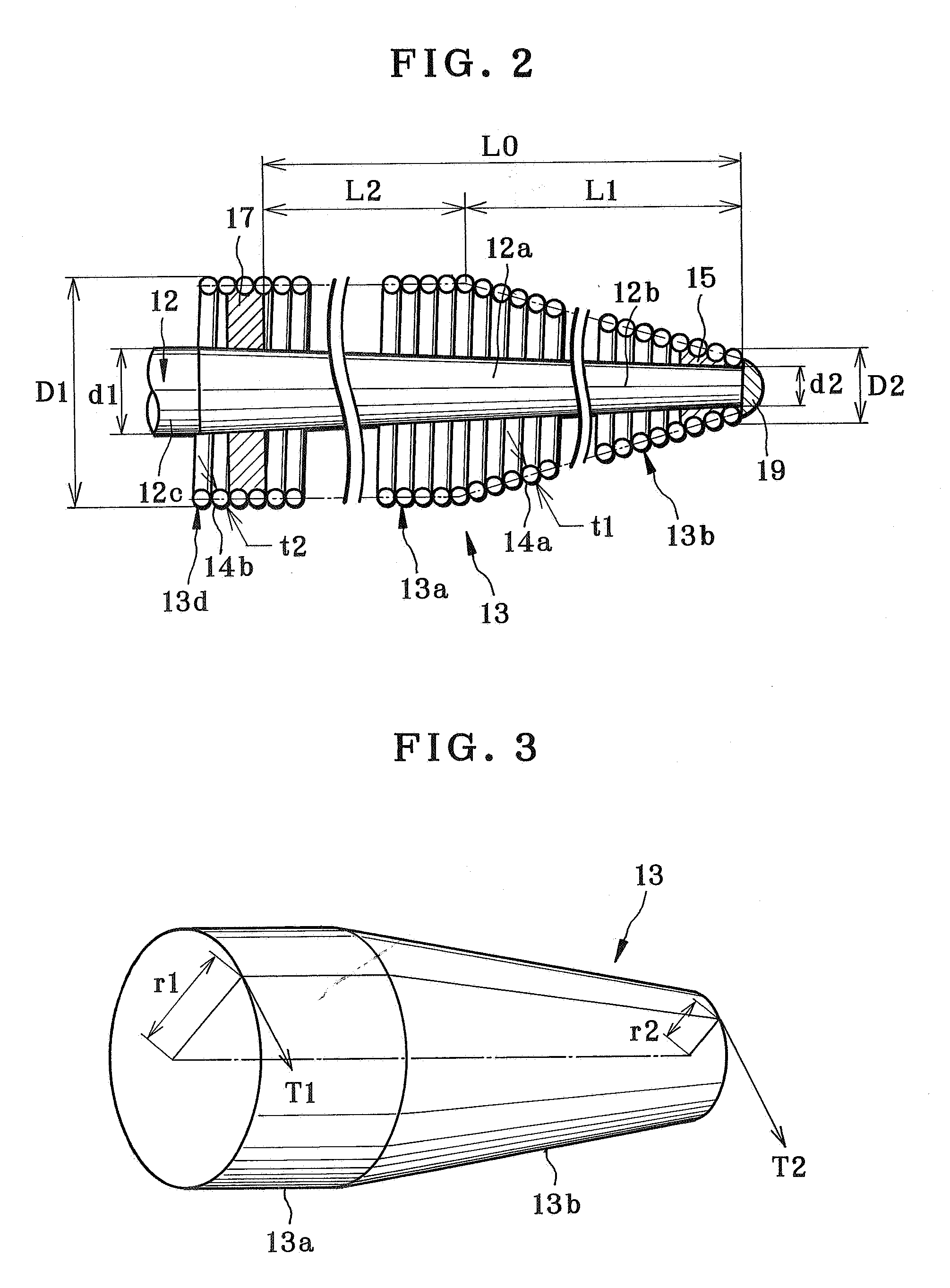
[0056]Various preferred embodiments with the core elongated component 12, the helical coil 13 and other portions are hereinafter described. In FIG. 2, a first embodiment is illustrated. The coil filament 14a of platinum has a filament diameter t1 of 0.065 mm, and is wound to define the diameter decreasing coil portion 13b and the equiradial coil portion 13a of the helical coil 13. The coil filament 14b of SUS 304 steel has a filament diameter t2 of 0.060 mm, and is wound by coiling to define the equiradial helical coil part 13d of the helical coil 13 from the middle connector 17 to the proximal side. The equiradial helical coil part 13d is attached to the equiradial coil portion 13a by the middle connector 17 with paraffin wax to obtain the helical coil 13. Note that the equiradial helical coil part 13d on the proximal side may not be wound tightly with a difference from the diameter decreasing coil portion 13b. The proximal end diameter D1 of the helical coil 13 is equal to or less...
third embodiment
[0074]In the third embodiment, as the length L2 is 6 mm, a spring constant is approximately 1.5 times as high as that of a helical coil of a fully equiradial form. The torsion angle and the spring deflection decrease because the spring constant increases. Also, the middle connector 17 is attached to the equiradial coil portion 13a. There is no point of attachment to the diameter decreasing coil portion 13b being inclined. No unwanted flow of paraffin wax occurs on the diameter decreasing coil portion 13b. So operation of dispensing paraffin wax can be carried out stably. Furthermore, strength of attachment with the core elongated component can be kept from lowering, because flowing away of paraffin wax is prevented.
[0075]A fourth embodiment is illustrated in FIG. 6. The first embodiment is repeated with a difference in that the equiradial coil portion 13a, which is positioned near to a proximal end of the diameter decreasing coil portion 13b having its greatest diameter, is associat...
eighth embodiment
[0080]In the eighth embodiment, a predetermined space C1 is defined between the core elongated component 12 and the helical coil 13, so intensity of attachment with the core elongated component 12 is ensured by higher flowability of paraffin wax into the space. The insertion of the core elongated component 12 into the helical coil 13 is facilitated to raise suitability for assembly. Performance of transmission of rotation to the core elongated component 12 can be high according to the high flowability and suitability for assembly. The distal end diameter D2 of the helical coil 13 is 0.253 mm. The filament diameter t1 of the helical coil 13 is 0.065 mm. Thus, the distal shaft diameter d2 is 0.0905 mm. As the proximal end diameter D1 of the helical coil 13 is 0.360 mm, and the proximal shaft diameter d1 of the core elongated component 12 is 0.1975 mm, rotational transmission of force from the proximal side to the distal side is approximately 2.18 times higher than an example in a regu...
PUM
 Abstract
Description
Claims
Application Information