
Method and System for Changing a Description for a State Transition Function of a State Machine Engine

Inactive Publication Date: 2007-12-06
IBM CORP
View PDF4 Cites 10 Cited by
  • Summary
  • Abstract
  • Description
  • Claims
  • Application Information

AI Technical Summary

Benefits of technology

[0026]A conflict resolution step implemented by a method that tries to determine one or more suggested ways to meet the conflic

Problems solved by technology

Support of wider input vectors as needed for a network traffic accelerator system, for example 32 bits, is much harder to implement in an efficient way at high processing rates, than to implement a state machine engine which processes input vectors consisting of only 8 bits, mainly because of the much larger set of possible input values that can occur.
Due to the high clock frequencies of today's processors it is therefore a challenging task to provide a ZuXA controller implementation for the use as a network traffic accelerator in computer systems with such high speed processors.
It is therefore beneficial to optimize the state machine engine implementation for that given subset of possible input values, enabling an efficient and fast implementation, rather than trying to cover all possible input values, resulting in an expensive and slow implementation.
However a problem exists wherein some of the input values, or combinations of input values, are not supported by the state machine engine implementation.

Method used


Image

  • Method and System for Changing a Description for a State Transition Function of a State Machine Engine
  • Method and System for Changing a Description for a State Transition Function of a State Machine Engine
  • Method and System for Changing a Description for a State Transition Function of a State Machine Engine

Examples


Embodiment Construction

[0038]In a first preparing step, a designer of a state machine engine needs to specify the state transition function for the FSM implemented by the state machine engine. FIGS. 5 and 6 are examples for state transition diagrams. In both figures Sk and Sn represent states, i1 to i5 represent some given input vector, and 1000b to 0001b represent a set of input vectors in binary representation.

[0039]The state diagram in FIG. 5 illustrates the following list of state transitions:[0040]Sk i1→Sk+1 [0041]Sk i2→Sk+2 [0042]Sk i3→Sk+3 [0043]Sk i4→Sk+4 [0044]Sk i5→Sk

[0045]Whereas the state diagram in FIG. 6 illustrates the following list of state transitions:[0046]Sn 1000b→Sn+1 [0047]Sn 1100b→Sn+2 [0048]Sn 1011b→Sn+3 [0049]Sn 0001b→Sn+4

[0050]For the preferred embodiment of the present invention, the list of state transitions needs to be derived from a state transition function description provided by the designer. This preparing step can be performed using well-known methods. The list of stat...


PUM


Abstract

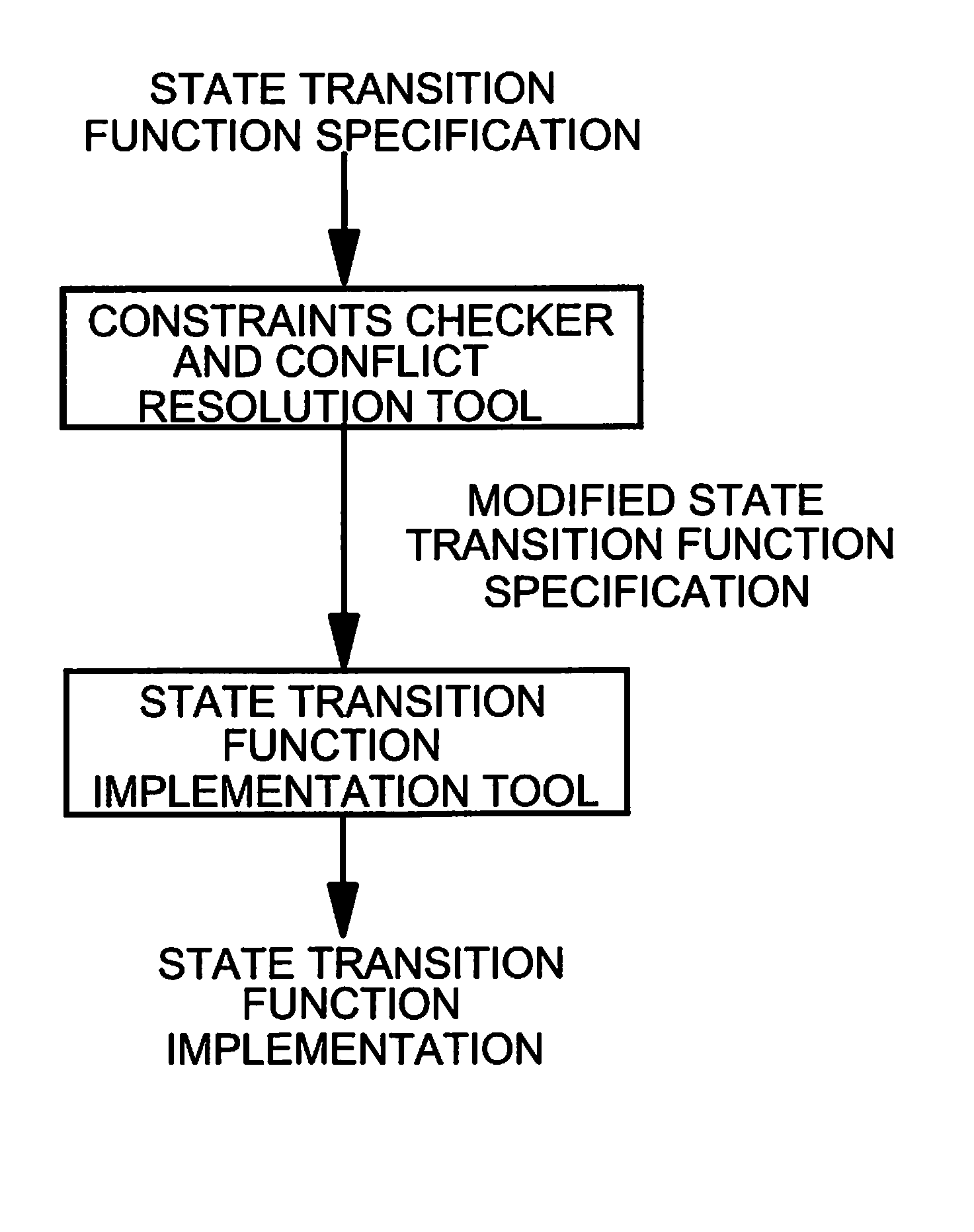
The invention relates to a method and system for the design and implementation of state machine engines. A first constraints checking step checks a state transition function created by a designer against constraints imposed by the implementation technology in order to detect all portions of the state transition function that are in conflict with the constraints. A subsequent conflict resolution step tries to determine one or more suggested ways to meet the conflicting constraints, by investigating how the original state transition function can be modified such that all constraints are met. A final presentation and selection step provides the designer textual and / or graphically results of the constraints check and suggested modifications. The modifications can be accepted interactively, or the state transition function can be changed manually. In the latter case, the modified state transition function will be processed starting again with the constraints checking step.

Description

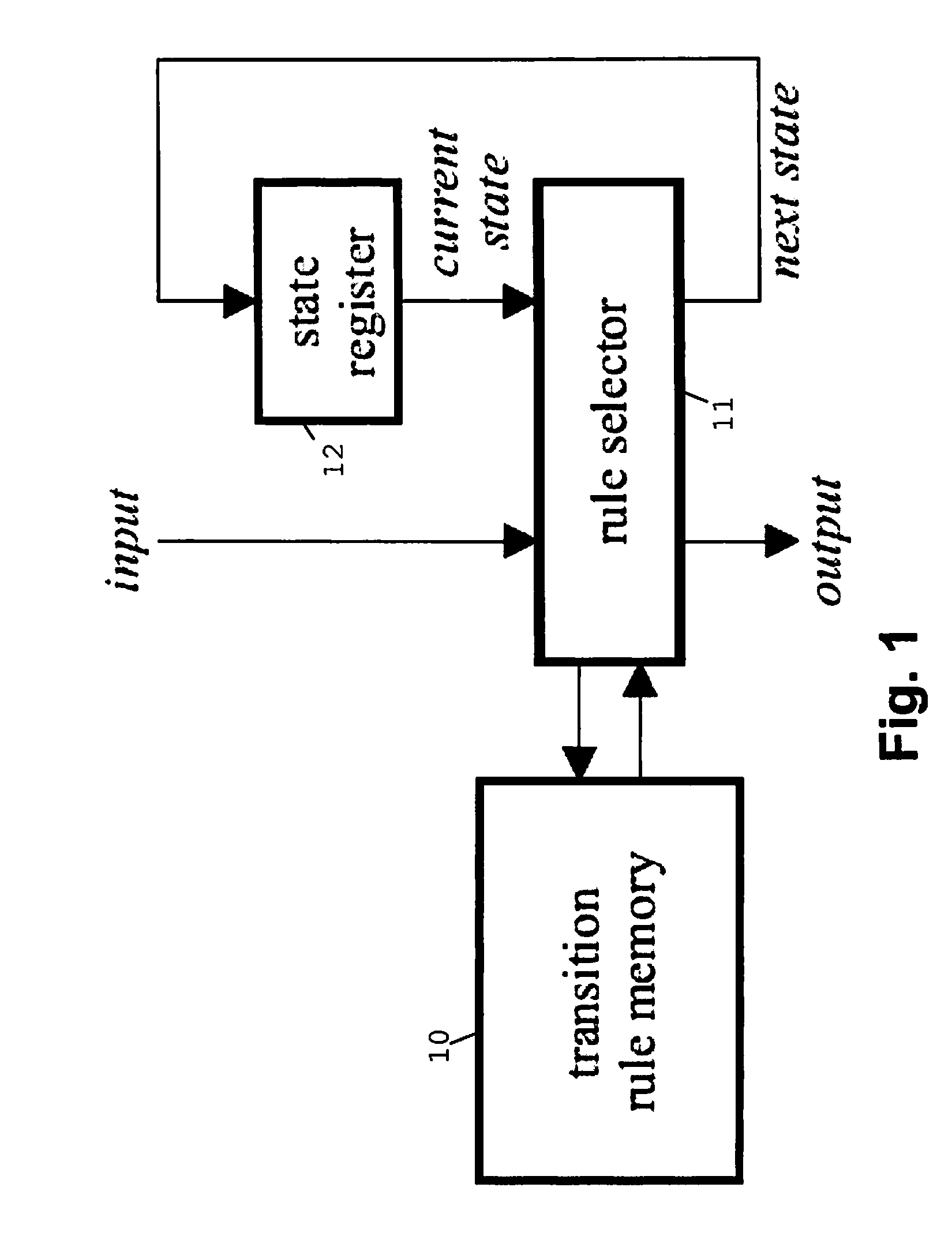
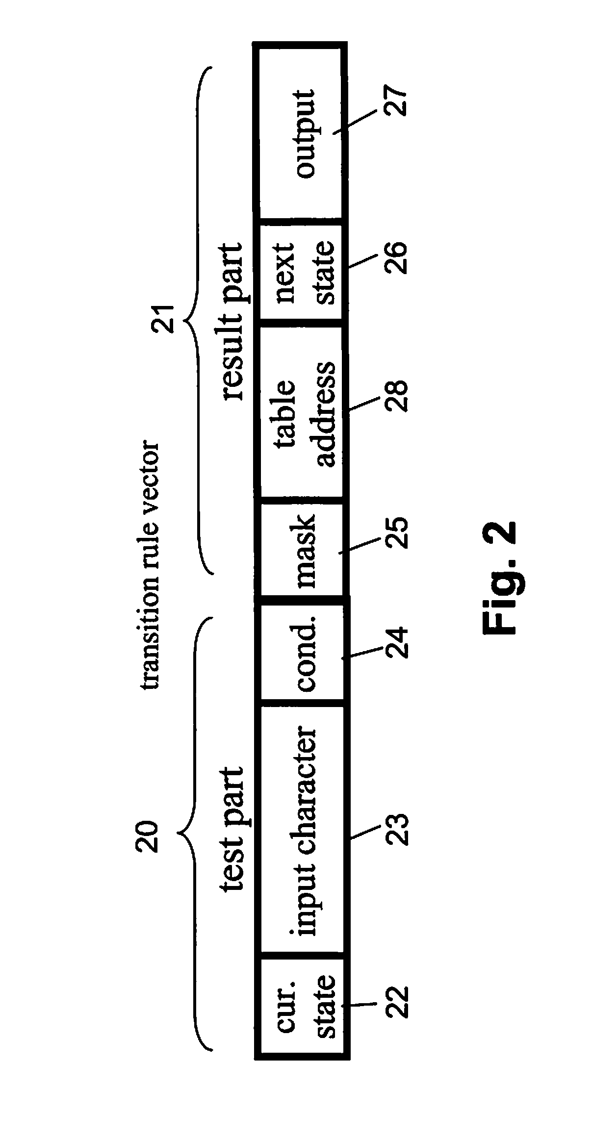
BACKGROUND OF THE INVENTION [0001]The present invention relates to the design and implementation of state machine engines in data processing systems.[0002]A finite state machine (FSM) is a model of behaviour composed of states, transitions and actions. A state stores information about the past, i.e., it reflects the input changes from the start to the present moment. A transition indicates a state change and is described by a condition that would need to be fulfilled to enable the transition. An action is a description of an activity that is to be performed at a given moment. A specific input action is executed when certain input conditions are fulfilled at a given present state. For example, an FSM can provide a specific output (e.g., a string of binary characters) as an input action.[0003]An FSM can be represented using a set of (state) transition rules that describes a state transition function. State transition diagrams are used to graphically represent FSMs. Classic forms of st...

Claims


Application Information

Patent Timeline
IPC IPC(8): G06F17/50
CPCG06F17/5045G06F30/30
Inventor FRITZ, ROLFKALTENBACH, MARKUSMAYER, ULRICHPFLUEGER, THOMASSTARKE, CORDTVAN LUNTEREN, JAN
Owner IBM CORP
Learn More