Method and system for dynamic reconfiguration of field programmable gate arrays

a field programmable gate array and dynamic reconfiguration technology, applied in pulse techniques, instruments, computation using denominational number representation, etc., can solve the problems of affecting the processing time of user programs, implementing anti-fuse technology, and either factory-programming fpga or implementing anti-fuse technology, so as to reduce the complexity of placemen

Inactive Publication Date: 2007-12-06
ATMEL CORP
View PDF6 Cites 62 Cited by
  • Summary
  • Abstract
  • Description
  • Claims
  • Application Information

AI Technical Summary

Benefits of technology

[0010]Implementations may provide one or more of the following advantages. An FPGA is provided that implements a supporting infrastructure in the static part that substantially operates in all configurations of the FPGA, and different user functions can be implemented on demand through dynamic reconfiguration. A software tool provides the means to place and route dynamically reconfigurable designs in the FPGA and also generate appropriate bitstream files. The described methods p

Problems solved by technology

None—the FPGA is either factory-programmed, or implements antifuse technology.
A common problem associated with dynamic reconfiguration of an FPGA, however, is that a pre-determined

Method used


Image

  • Method and system for dynamic reconfiguration of field programmable gate arrays
  • Method and system for dynamic reconfiguration of field programmable gate arrays
  • Method and system for dynamic reconfiguration of field programmable gate arrays

Examples


Embodiment Construction

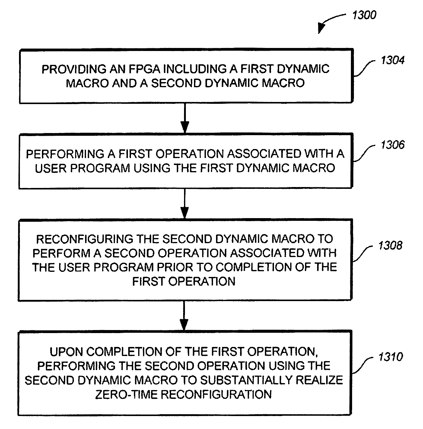
[0028]The present invention relates generally to digital circuits, and more particularly to dynamic reconfiguration of field programmable gate arrays (FPGAs). The following description is presented to enable one of ordinary skill in the art to make and use the invention and is provided in the context of a patent application and its requirements. Various modifications to the preferred implementations and the generic principles and features described herein will be readily apparent to those skilled in the art. Thus, the present invention is not intended to be limited to the implementations shown but is to be accorded the widest scope consistent with the principles and features described herein.

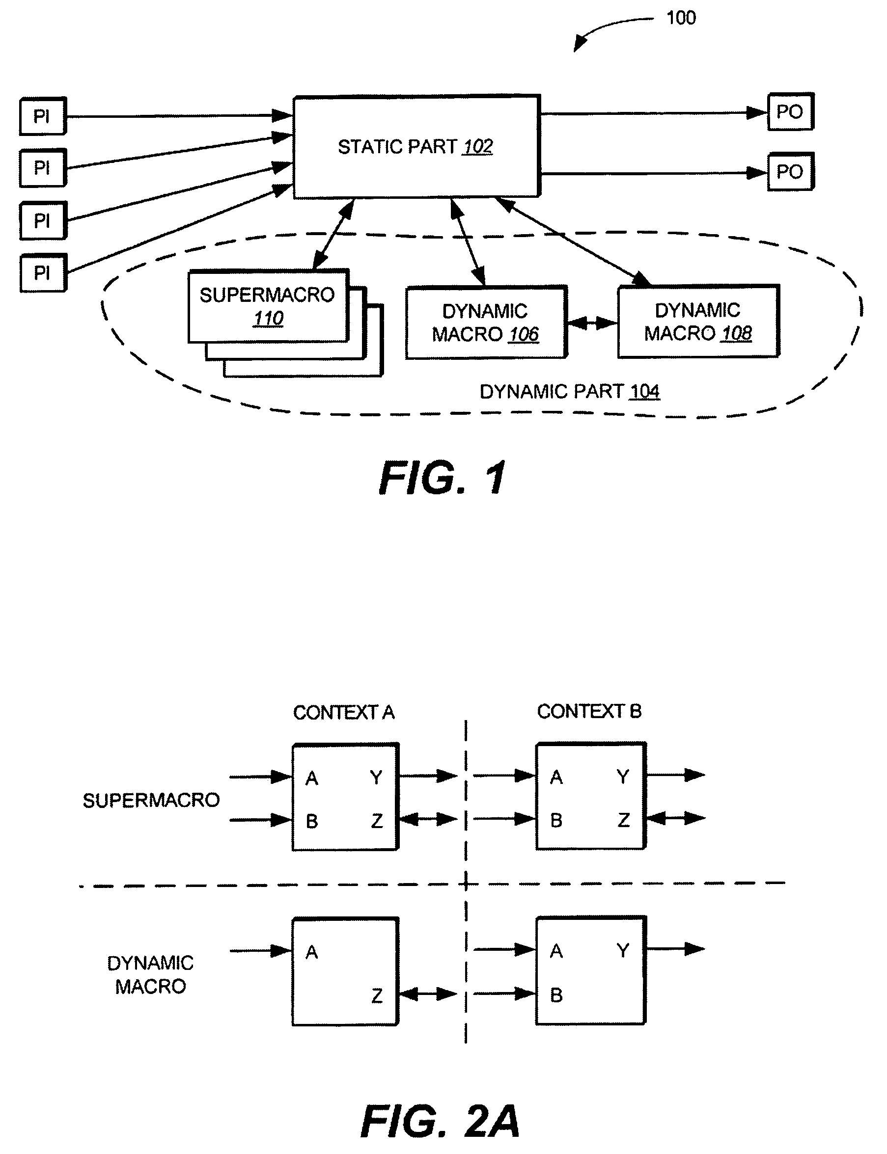
[0029]FIG. 1 illustrates a block diagram of an FPGA 100 according to one implementation of the invention. FPGA 100 includes a static part 102 and a dynamic part 104. In one implementation, static part 102 corresponds to logic within FPGA 100 that must always be present and running within FPGA 10...


PUM


Abstract

A field programmable gate array (FPGA) and methods for executing operations using an FPGA are provided. The method includes providing a first dynamic macro and a second dynamic macro in the FPGA. The first dynamic macro and the second dynamic macro each represent logic within the FPGA that can be reconfigured. The method further includes executing a first operation associated with the user application using the first dynamic macro; reconfiguring the second macro to execute a second operation associated with the user application prior to completion of the first operation; and upon completion of the first operation, executing the second operation using the second dynamic macro.

Description

FIELD OF THE INVENTION[0001]The present invention relates generally to digital circuits, and more particularly to dynamic reconfiguration of field programmable gate arrays (FPGAs).BACKGROUND OF THE INVENTION[0002]Field programmable gate arrays (FPGAs) are a class of programmable logic devices. FPGAs generally feature a gate array architecture with a matrix of logic cells surrounded by a periphery of input / output (I / O) cells (or pins). Logic within the gate array architecture can be reconfigured (or re-programmed) after an FPGA has been manufactured, rather than having the programming fixed during manufacturing. Accordingly, with an FPGA, a design engineer is able to program electrical connections on-site for a specific application (for example, a device for a sound / video accelerator card).[0003]Reconfiguration of an FPGA can be classified according to two basic criteria—the method of reconfiguration and the amount of reconfiguration logic in terms of device (FPGA) size. With respect...

Claims


Application Information

Patent Timeline
IPC IPC(8): G06F17/50
CPCG06F17/5054G06F30/34
Inventor KAROUBALIS, THEODORENASI, KELLYKADLEC, JIRIDANEK, MARTINMATOUSEK, RUDOLF
Owner ATMEL CORP
Why Eureka
Try Eureka