Measuring array

a technology of measuring arrays and arrays, applied in the field of measuring arrays, can solve the problems of poor measurement accuracy and increased relative measurement errors, and achieve the effects of less safety loading, high measurement accuracy, and poor measurement accuracy

Active Publication Date: 2007-12-13
SMA SOLAR TECH AG
View PDF6 Cites 51 Cited by
  • Summary
  • Abstract
  • Description
  • Claims
  • Application Information

AI Technical Summary

Benefits of technology

[0022]A major advantage of the invention is that high accuracy measurement is also possible in case of several leakage resistances. Meaning, the measurement array is also perfectly operative if leakage resistances Rn and Rp occur at the same time or if an insulation error occurs at a point that is not located on the positive or the negative pole, for example in the center of a solar generator. With a simple prior art array as described in FIG. 2, the calculated insulation resistances would be higher than in reality so that the user would feel erroneously safe. Even with the improved arrays according to the documents EP 1 265 076, DE 35 13 849 and EP 0 833 423, the possibly to achieve measurement accuracy is poorer so that the improved measurement of the invention requires less safety loadings, this meaning that the failure frequency of the installation is reduced at a limit value for Riso that is to be observed. Accordingly, the operator of the installation is offered an installation that is more available and more secure at the same time.
[0023]In a second implementation of the invention in accordance with claim 3, the two voltage measurement systems may be replaced with only one current measurement apparatus between the connection point of the two switches and earth (FIG. 4). Then, the two resistances Rs are no longer needed for measurement so that their tolerances will no longer be included in the measurement accuracy. Like in the first implementation, the measurement is run so that a PE conductor (earth) is connected successively, via a switching component, for example a relay, to the positive and to the negative pole of the supply voltage, the respective currents in the switched connections being now measured.
[0024]If IPE is the current when switch S1 is closed and switch S2 open and IPE, the current when switch S2 is closed and S1 open, we have
[0025]Due to the difference measurement, an offset error of the current measurement has no influence on the calculated Riso value so that measurement accuracy is again improved.
[0026]In a preferred third embodiment in accordance with claim 4 of the invention, the complex potential free current measurement is relocated to one of the two poles of the installation so that the evaluation is easier to perform by a microprocessor having a corresponding reference potential (FIG. 5). For this purpose, a switch S2 is not connected directly to a pole, but via a current source that needs a supply voltage that is negligible compared to the operating voltage UB. This supply voltage is made available by an accordingly actuated transistor, e.g., by a bipolar transistor having the highest possible current amplification or by a field effect transistor. The collector or drain connection of the transistor is connected to the connection of the second switch S1 that is not connected with PE. A current measurement system is connected between this connection point and the second pole. If Ipos is the current when the switch S1 is closed and the switch S2 open and if Ipos′ is the current when the switch S2 is closed and the switch S1 open, one has
[0027]Again, thanks to the difference measurement, both offset errors of the current measurement and scatterings of the current source do not enter into the calculation so that here also the measurement accuracy obtained is high. For ease of measurement evaluation by a microcontroller, the current Ipos may be lead through a shunt that is connected to an AC / DC converter in the microcontroller. The microcontroller may then register one after the other the measurement values for UB, Ipos and Ipos′ and calculate Riso.

Problems solved by technology

The disadvantage of this array is the poor measurement accuracy if a low-impedance insulation fault is to be determined in parallel to the connected branch.
Accordingly, the relative measurement error increases a lot.
The disadvantage thereof is that for computing the leakage resistances Rn(RL1) and Rp (RL2), it is necessary to measure two respective instantaneous values of two different voltages and to know the exact value of the additionally connected resistance.
Since in practice all the measurands are afflicted with an error, the measurement errors of the two voltages enter into the computed resistance values.

Method used


Image

  • Measuring array
  • Measuring array
  • Measuring array

Examples


first embodiment

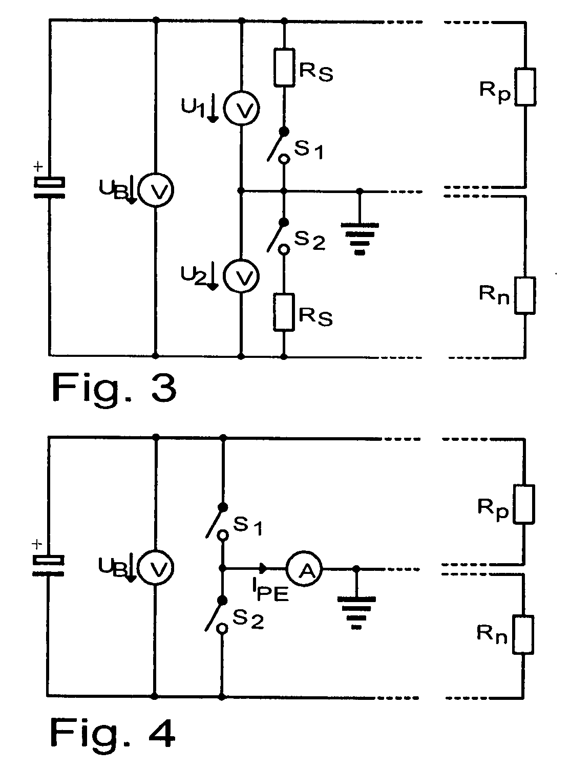
[0041]FIG. 3 shows the invention. The structure shown is also used in the document EP 0 833 423. In accordance with the invention, a measurement cycle is defined thus that a first measurement is performed with the switch S1 being closed and the switch S2 open and that next a second measurement is performed with the switch S2 being closed and the switch S1 open. As already mentioned, this results in simple equations with little fault influence.

second embodiment

[0042]FIG. 4 shows the invention. A current measurement system is hereby provided between earth 5 and the connection point of the two switches in order to measure the current for calculating the insulation resistance. The measurement cycle remains unchanged with respect to the rule in FIG. 3.

third embodiment

[0043]FIG. 5 shows a preferred third embodiment of the invention. Here, the current measurement performed is indirect. The circuit makes use of an additional constant current source that supplies the constant current Iconst. The switch S2 is not directly connected to the positive pole, but via the current source. In addition thereto, a MOSFET having an appropriate actuation UG is connected in parallel with the two switches S1 and S2. The advantage thereof is that, instead of measuring the current IPE with respect to earth 5, a current Ipos is measured with respect to the positive pole of the installation. Thus the current may be measured readily, e.g., via a shunt, with a microprocessor the reference potential of which is located on this pole. Like in the implementation in FIG. 4, this solution allows for accurate measurement without highly accurate resistances.

[0044]With the method discussed and the measurement arrays described, the insulation resistance Riso of an energized electr...


PUM


Abstract

The invention relates to a measuring array with an earth connection point (5) for determining the insulation resistance (Riso) of an energized electrical apparatus or of an installation with a supply voltage UB with a positive pole (6) and a negative pole (7), two switches (S1, S2) or a corresponding two-way switch being provided for creating a current path between one of the two poles and said earth connection point (5) in order to determine the insulation resistance (Riso) generally obtained when one or a plurality of insulation faults occur at any potential reference, two measurements being performed one after the other for determining the insulation resistance, the first switch (S1) being closed and the second switch (S2) open during the first of these two measurements and the first switch (S1) being open and the second switch (S2) closed during the second of these measurements.

Description

CROSS-REFERENCE TO RELATED APPLICATIONS[0001]This application claims Priority from German Application No. De 10 2006 022 686.0-35 filed on 16. May 20061 FIELD OF THE INVENTION[0002]The invention relates to a measuring array with an earth connection point for determining the insulation resistance (Riso) of an energized electrical apparatus or of an installation with a supply voltage (UB) with a positive pole and a negative pole, two switches (S1 and S2) or a corresponding two-way switch being provided for creating a current path between one of the two poles and the earth connection point in order to determine the insulation resistance (Riso) generally obtained when one or a plurality of insulation faults occur at any potential reference.[0003]In electrical installations, faults due to moisture, dirt, shorts or other causes may occur in the insulation between a voltage-carrying installation part and earth.[0004]In grounded electrical installations, such a fault immediately results in ...

Claims


Application Information

Patent Timeline
Patent Type & Authority Applications(United States)
IPC IPC(8): G01R31/08
CPCG01R27/18Y02E10/50
Inventor MULLER, BURKARD
Owner SMA SOLAR TECH AG
Why Eureka
Try Eureka