
Extended read range RFID system

a radio frequency identification and read-only technology, applied in the direction of instruments, electrical signalling details, burglar alarm mechanical actuation, etc., can solve the problems of limited life span, inconvenient operation, and large antennas,

Inactive Publication Date: 2007-12-13
BROOKS AUTOMATION HLDG LLC +2
View PDF12 Cites 11 Cited by
  • Summary
  • Abstract
  • Description
  • Claims
  • Application Information

AI Technical Summary

Benefits of technology

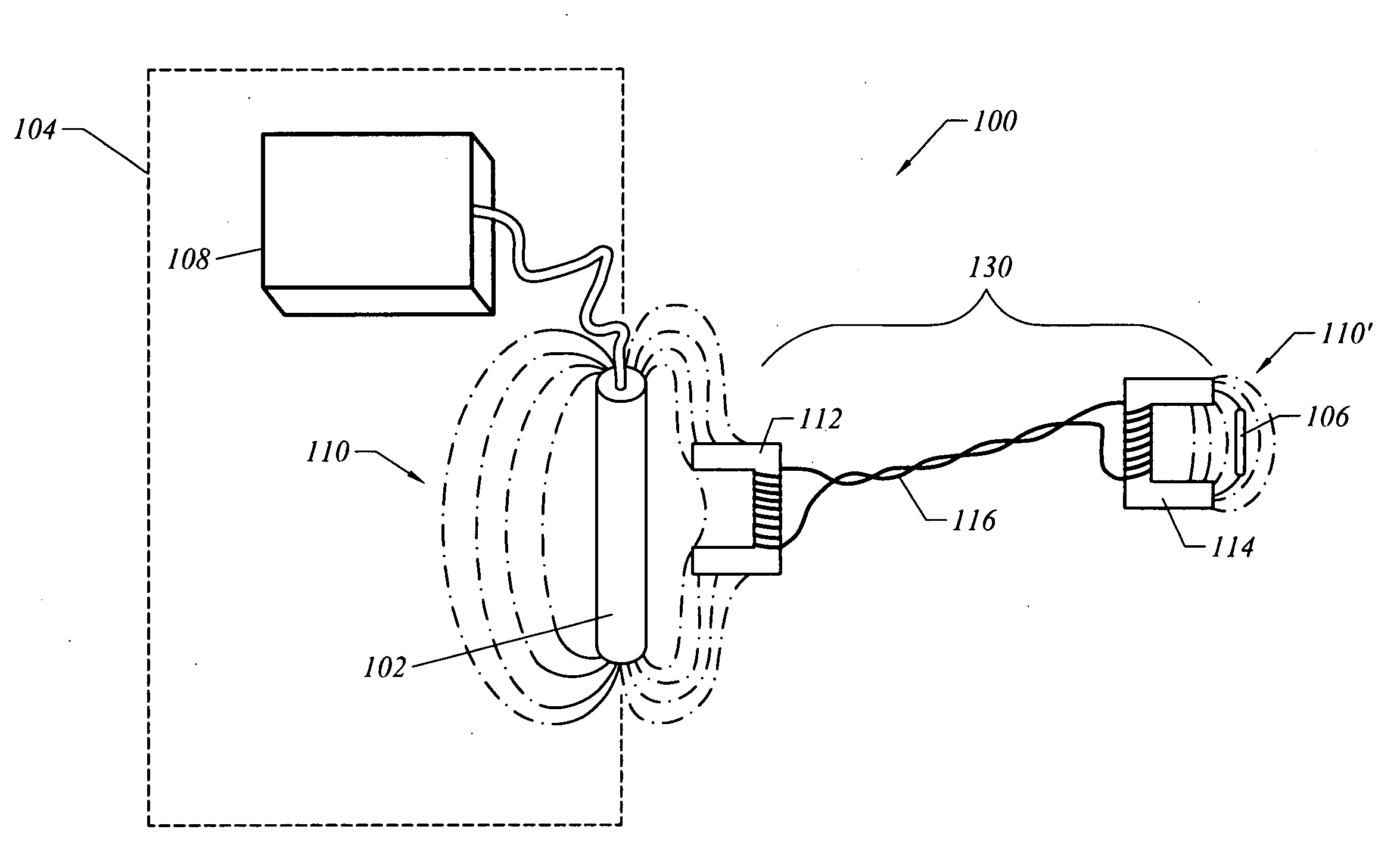
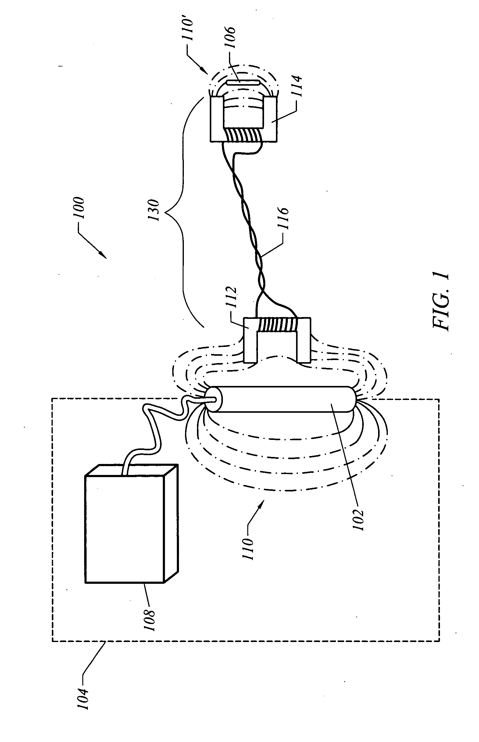
[0012]One aspect of the present invention is to provide a low cost solution to increase the read range of RFID tags. In one embodiment, the present invention comprises an RFID bridge that transmits an RF field emitted by an antenna proximate to an RFID tag located on a container seated in a storage location. The distance between the antenna and the RFID tag is increased many order of times compared to what is possible with conventional RF antenna and RFID tag placements.
[0013]Another aspect of the present invention is to provide an RFID system that minimizes the number of RFID readers required to read multiple RFID tags. In one embodiment, the present invention comprises a system whereby an RFID bridge is dedicated to each container storage location. A single RF antenna may be maneuvered between each pickup device of each RFID bridge and obtain the information stored in the RFID tag of each container.
[0016]Another aspect of the present invention is to provide an RFID system that may quickly obtain the information stored in the RFID tags of several containers. In one embodiment, a storage location includes multiple storage areas for storing, for example, three containers. With a dedicated RFID bridge for each storage area, an antenna may be maneuvered, sometimes only a matter of inches between each pickup coil, in order to quickly obtain the information stored in each RFID tag. The containers do not have to be movesd at all to obtain this information.

Problems solved by technology

Even though some of these devices are built to have up to a 10 year life span, they have limited life spans.
Both passive and active tag RFID systems have a common limitation of read range to approximately 1 meter, and to even reach 1 meter efficiently, the antenna needs to be very large and therefore is expensive.
RFID tags can be read in a wide variety of circumstances, where barcodes or other optically read technologies are useless.
RFID system present unique challenges in a semiconductor manufacturing environment or fabrication facility.
The enormous number of RFID readers adds additional cost to RFID operation.
Reading the RFID tags on each container is challenging.
Obviously, this process is very resource and time consuming.
Further, while this audit process is in progress, no other work can be executed.
Thus, the audit process severely limits or reduces the fab's productivity.
Placing an RFID reader on each storage shelf, on the other hand, is a very expensive and complex solution.

Method used


Image

  • Extended read range RFID system
  • Extended read range RFID system
  • Extended read range RFID system

Examples


Embodiment Construction

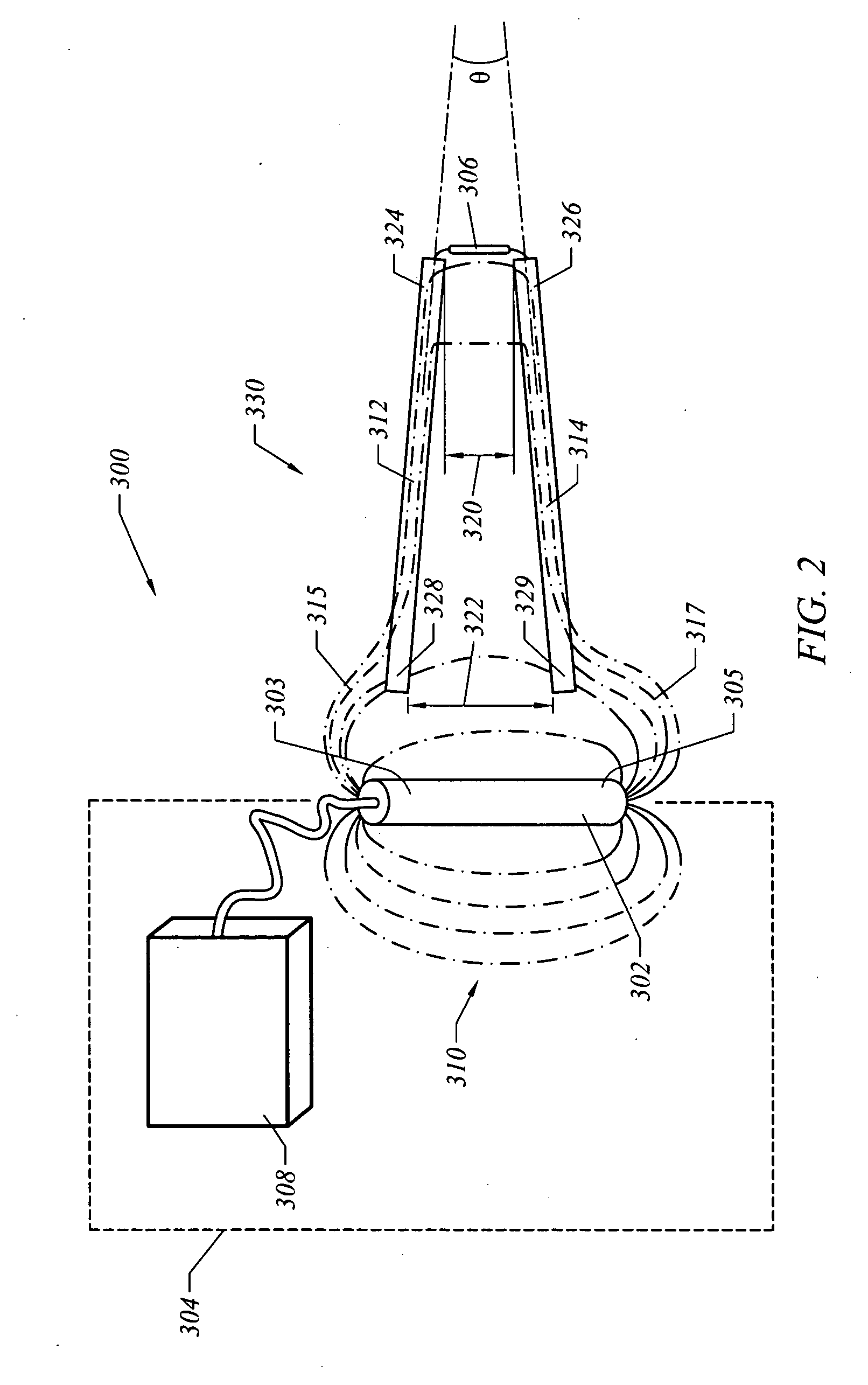
[0026]The present invention disclosed herein and illustrated in FIGS. 1-9 provides various systems for conveying a radio-frequency (RF) field between a powered antenna and an RFID tag. The many embodiments of the present invention are suitable for applications where the RFID reader is moving with respect to the container storage location or vice versa.

[0027]FIG. 1 illustrates an RFID system 100. In this embodiment, the RFID system 100 includes, among other things, an transmitting device 102, an RFID reader 108, an RFID tag 106 and an RFID bridge 130. The RFID transmitting device 102 and RFID reader or interrogator 108 may be housed in any number of mechanisms or devices 104. In one embodiment, the RFID transmitting device 102 and RFID reader 108 are housed in a transportation vehicle 104, such as an overhead transport (OHT) vehicle. In another embodiment, the RFID transmitting device 102 and RFID reader 108 are housed and maneuvered by a robotic arm mechanism 104 (see FIG. 9, descri...


PUM


Abstract

The present invention generally comprises an apparatus that allows an RFID antenna to obtain information from an RFID tag mounted on a container. The apparatus reproduces the RF field generated by the antenna to a location proximate to the RFID tag. In one embodiment, the apparatus comprises a pickup device and a reproduction device electrically coupled with the pickup device. In another embodiment, the apparatus comprises at least one magnetic rod, which creates a magnetic path for the RF field to travel between the antenna and the RFID tag. In another embodiment, the apparatus comprises a pickup antenna and a reproduction antenna for transmitting the RF signal from the antenna proximate to the RFID tag.

Description

FIELD OF THE INVENTION[0001]The present invention generally relates to an improved Radio Frequency Identification (RFID) system. More specifically, the present invention comprises an RFID system for a semiconductor manufacturing facility.BACKGROUND OF THE INVENTION[0002]A conventional RFID system has three parts: (i) a scanning antenna, (ii) a transceiver with a decoder to interpret the data, and (iii) a transponder—the radio-frequency tag—that has been programmed with information[0003]The scanning antenna puts out radio-frequency signals in a relatively short range. The radio-frequency (RF) radiation does two things. It provides a way of communicating with the transponder tag (e.g., the RFID chip) and, in the case of passive RFID tags, it provides the RFID device with the energy to communicate. RFID devices do not need to contain batteries, and can therefore remain usable for very long periods of time.[0004]The scanning antennas can be permanently affixed to a surface. Handheld ant...

Claims


Application Information

Patent Timeline
Patent Type & Authority Applications(United States)
IPC IPC(8): G08B13/14G08B1/08
CPCG06K7/10178G06K7/0008
Inventor SHARMA, ARUNFRITSCHEN, DANIELLIU, DANIELRILEY, NORMA
Owner BROOKS AUTOMATION HLDG LLC
Learn More