Display device, sensor panel, position-detecting device, position-inputting device, and computer system

Active Publication Date: 2007-12-13
WACOM CO LTD
View PDF3 Cites 30 Cited by
  • Summary
  • Abstract
  • Description
  • Claims
  • Application Information

AI Technical Summary

Benefits of technology

[0032] According to embodiments of the present invention, a sensor panel including detection conductors can be provided on a display surface of a display device without reducing the visibility of a screen of the display device. Accordingly, the effect of magnetic noise from a rear surface of t

Problems solved by technology

Typically, a display device such as a liquid crystal display device generates a lot of noise.
Also, if other devices such as a substrate and the like are provided below a display device in an overlapped manner, a lot of noise is brought about by those devices

Method used


Image

  • Display device, sensor panel, position-detecting device, position-inputting device, and computer system
  • Display device, sensor panel, position-detecting device, position-inputting device, and computer system
  • Display device, sensor panel, position-detecting device, position-inputting device, and computer system

Examples


example 1

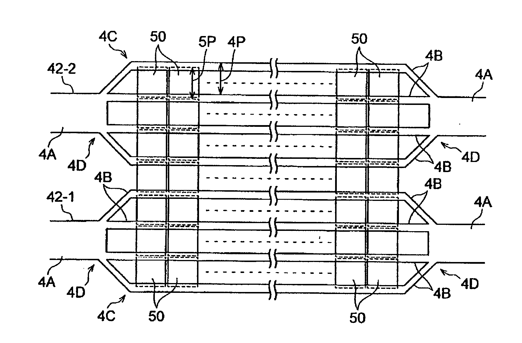
[0136]FIG. 9 is an enlarged plan view illustrating a structure of loop coils according to an exemplary embodiment of the present invention.

[0137] In FIG. 9, loop coils 42-1 and 42-2 are illustrated as an example. The structure of all the loop coils in loop coil groups 42 and 44 may be similar to the structure of the loop coils 42-1 and 42-2 illustrated in FIG. 5.

[0138] In the structure illustrated in FIG. 9, instead of the branch-connecting portion 4D of the loop coils 42-1 and 42-2 in the above-mentioned embodiment, a branch-connecting portion 4E is provided. The branch-connecting portion 4E is a portion where the base line portion 4A meets the narrow lines 4B (i.e., a connection portion). The branch-connecting portion 4E is made of a conductor similar to the base line portion 4A and the narrow lines 4B. The branch-connecting portion 4E has a shape which expands between narrow line portions 4C at both ends of the narrow lines 4B, outside of a display region of the display panel 5...

example 2

[0139]FIG. 10 is a cut out perspective view illustrating a structure of a display panel according to another exemplary embodiment of the present invention.

[0140] In this example, loop coils of loop coil groups 42 and 44 are formed inside a liquid crystal display panel 6.

[0141] The liquid crystal display panel 6 illustrated in FIG. 10 includes a polarization plate 61, a glass substrate 62 disposed on the polarization plate 61, a transparent conductor layer 63 disposed on the glass substrate 62, a liquid crystal layer 64 disposed on the transparent conductor layer 63, a transparent conductor layer 65 disposed on the liquid crystal layer 64, a color filter 66 disposed on the transparent conductor layer 65, a glass substrate 67 disposed on the color filter 66, and a polarization plate 68 disposed on the glass substrate 67. The liquid crystal display panel 6 emits light from below, for example, by using a cold-cathode tube backlight.

[0142] The liquid crystal display panel 6 is divided...


PUM

PropertyMeasurementUnit
Widthaaaaaaaaaa
Widthaaaaaaaaaa
Angleaaaaaaaaaa

Abstract

A display device is provided. The display device includes a display screen having a light-transmissible display conductor extending in a predetermined plane, and at least one detection conductor extending along the predetermined plane, the at least one detection conductor having at least one base line portion formed of a conductor of a first width and a narrow line portion including a plurality of narrow-line conductors of a second width connected in parallel between the at least one base line portion.

Description

CROSS REFERENCES TO RELATED APPLICATIONS [0001] The present application claims priority from Japanese Application No. P2006-078959 filed on Mar. 22, 2006, which application is incorporated herein by reference and to which priority is claimed. FIELD OF THE INVENTION [0002] The present invention relates to a display device, a sensor panel provided in the display device, a position-detecting device including the sensor panel, a position-inputting device having the position-detecting device and a position indicator, and a computer system including the position-inputting device. BACKGROUND OF THE INVENTION [0003] Generally, position-detecting devices which detect positions indicated by pen-type position indicators are known. For example, Japanese Published Patent Application No. 2002-215317 discloses a product in which a position-detecting device integrally formed with a liquid crystal display device is used and a position-inputting operation can be carried out by operating a position in...

Claims


Application Information

Patent Timeline
IPC IPC(8): G09G5/08B05D5/12
CPCG06F3/03545G06F2203/04103G06F3/046G06F3/0412G06F3/04184
Inventor ITO, MASAMITSU
Owner WACOM CO LTD
Why Eureka
Try Eureka