
Liquid crystal display and fabrication method thereof

a technology of liquid crystal display and fabrication method, which is applied in the direction of instruments, non-linear optics, optics, etc., can solve the problems of complicated fabrication process and damage of the pad, and achieve the effect of simplifying the fabrication process of the lcd and reducing the amount of metal particles

Inactive Publication Date: 2007-12-13
LG DISPLAY CO LTD
View PDF3 Cites 7 Cited by
  • Summary
  • Abstract
  • Description
  • Claims
  • Application Information

AI Technical Summary

Benefits of technology

The present invention is a liquid crystal display and its fabrication method that solves problems associated with current technology. The invention provides a display with holes at predetermined locations on the pad part of the thin film transistor, which simplifies the process of removing the shorting bar and reduces metal particles during the fabrication process. The invention also includes a method for fabricating the display by attaching an upper substrate with a thin film transistor array and a lower substrate with a color filter and a black matrix, forming holes at the inner upper portion of the pads, scribing the holes to remove the shorting bar, and dividing the substrates into panels. The technical effects of the invention include reducing metal particles, simplifying the fabrication process, and improving the quality of the liquid crystal display.

Problems solved by technology

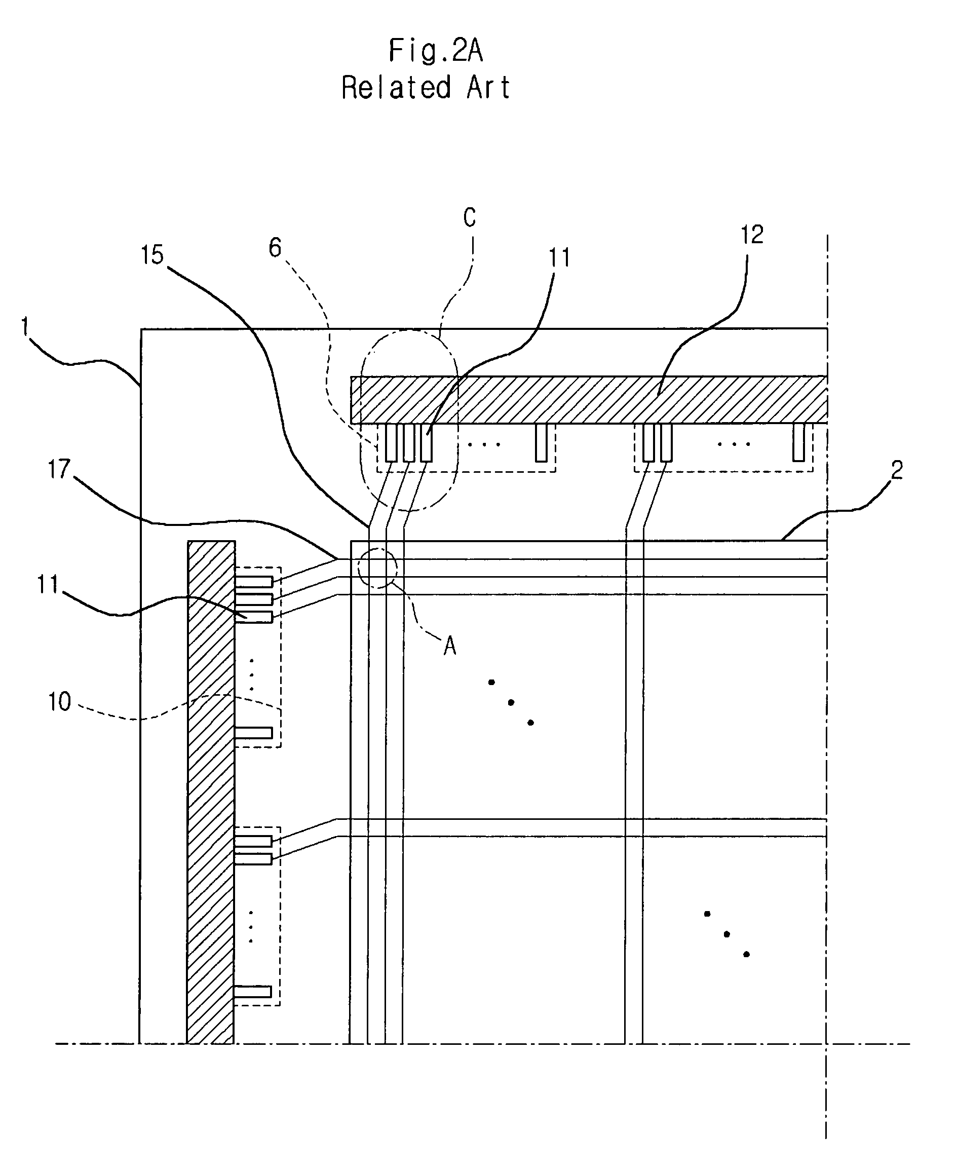
However, if the shorting bar is removed as above, the shorting bar of metal may generate a lot of particles during the removal process, so that the pad may be damaged.
In addition, the scribing process and the grinding process essentially used for removing the shorting bar make the fabrication process of the LCDs complicated.

Method used


Image

  • Liquid crystal display and fabrication method thereof
  • Liquid crystal display and fabrication method thereof
  • Liquid crystal display and fabrication method thereof

Examples


Embodiment Construction

[0049] Reference will now be made in detail to embodiments of the present invention, examples of which are illustrated in the accompanying drawings. The present invention is not limited to the embodiments. It will be apparent to those skilled in the art that various modifications and variations can be made in the present invention.

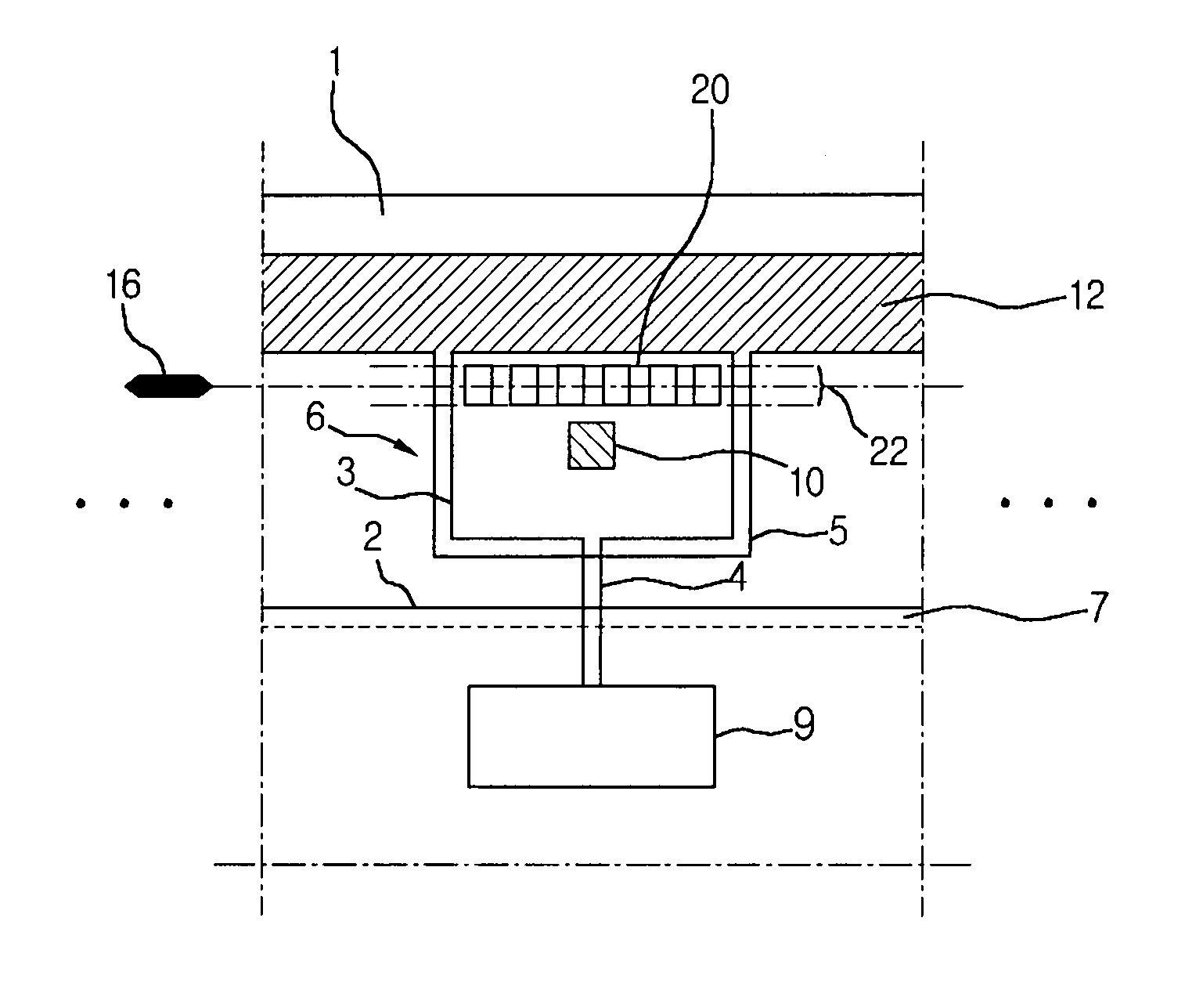
[0050]FIGS. 4A and 4B are plan views illustrating a drive circuit, a pad part and a shorting bar formed on a lower substrate of an LCD according to the present invention. Specifically, FIGS. 4A and 4B illustrate a specific portion of a polycrystalline silicon TFT LCD, i.e., a region corresponding to the specific portion (B) of FIG. 2B according to the related art.

[0051] In the above, the polycrystalline silicon TFT means that the active region of a thin film transistor (TFT) provided in each pixel region of an LCD, i.e., a channel region, is formed of polycrystalline silicon.

[0052] Referring to FIGS. 4A and 4B, an LCD according to the invention includes...


PUM

PropertyMeasurementUnit
light transmittanceaaaaaaaaaa
electric fieldaaaaaaaaaa
anglesaaaaaaaaaa

Abstract

Disclosed is a method for fabricating a liquid crystal display. The method includes the steps of: forming a lower substrate and an upper substrate, the lower substrate including a data drive circuit connected with data lines of a thin film transistor array and a gate drive circuit connected with gate lines of the thin film transistor array, a pad part connected with the gate drive circuit and the data drive circuit, and a shorting bar connected with the pad part, the upper substrate including a color filter and a black matrix; dispensing a spacer on the lower substrate and forming a seal pattern at a display region on the upper substrate; attaching the lower substrate and the upper substrate to face with each other and then forming holes at an inner upper portion of the pads at a predetermined distance; scribing the holes-formed-portion of the pads to remove the shorting bar and dividing the attached upper and lower substrates into a plurality of LCD panels; and providing a liquid crystal layer between the upper and lower substrates.

Description

[0001] This application claims the benefit of Korean Patent Application No. 2002-66790, filed on Oct. 31, 2002, which is hereby incorporated by reference for all purposes as if fully set forth herein. [0002] This application incorporates by reference two co-pending applications, Ser. No. 10 / 184,096, filed on Jun. 28, 2002, entitled “SYSTEM AND METHOD FOR MANUFACTURING LIQUID CRYSTAL DISPLAY DEVICES” (Attorney Docket Number 8733.666.00) and Ser. No. 10 / 184,088, filed on Jun. 28, 2002, entitled “SYSTEM FOR FABRICATING LIQUID CRYSTAL DISPLAY AND METHOD OF FABRICATING LIQUID CRYSTAL DISPLAY USING THE SAME” (Attorney Docket Number 8733.684.00), as if fully set forth herein.BACKGROUND OF THE INVENTION [0003] 1. Field of the Invention [0004] The present invention relates to a liquid crystal display, and more particularly, to a liquid crystal display structure with a simplified fabrication process, and a fabrication method thereof [0005] 2. Discussion of the Related Art [0006] Generally, a ...

Claims


Application Information

Patent Timeline
Patent Type & Authority Applications(United States)
IPC IPC(8): G02F1/1341G02F1/13G02F1/1345G02F1/1333G02F1/1362
CPCG02F1/133351G02F1/136204G02F1/13458G02F1/1345
Inventor CHO, SO HAENGCHUNG, HYUN SANG
Owner LG DISPLAY CO LTD
Learn More