
Antenna with lighting function

a technology of lighting function and antenna, applied in the field of antennas, can solve the problems of strict restrictions on signals, signal transmission quality, antenna base stations, etc., and achieve the effect of improving the utilization rate of spa

Inactive Publication Date: 2007-12-13
SMARTANT TELECOMM
View PDF5 Cites 17 Cited by
  • Summary
  • Abstract
  • Description
  • Claims
  • Application Information

AI Technical Summary

Benefits of technology

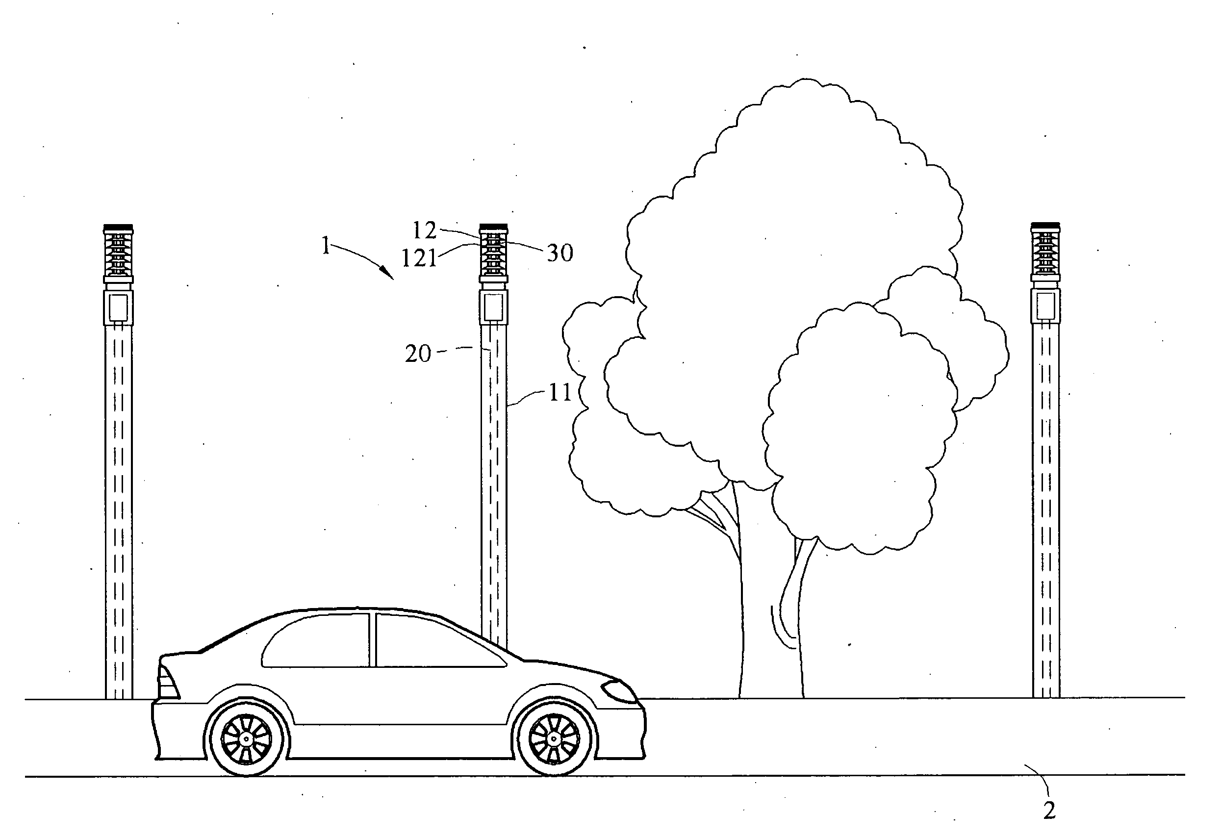
[0009]In view of the above problems of the conventional art, the present invention is directed to an antenna with a lighting function, which conceals an antenna component to realize camouflage and protection effects, and provides an additional lighting function, such that the antenna is combined with general public facilities to improve the space utilization rate.
[0011]The advantages of the present invention are described as follows. As the antenna component is accommodated within the accommodation body in the present invention, the functions of both camouflaging and protecting the antenna component can be achieved, so as to relieve the mass' concerns about the antenna, and to reduce the damages to the antenna component, which further reduces the maintenance cost. Meanwhile, the present invention integrates the lighting function, such that the antenna can serve as a street lamp as well, so as to reduce the competition on space between the antenna and general public facilities, and thus improving the space utilization rate.

Problems solved by technology

However, in order to obtain desirable voice quality, the power of the signals is often adjusted, and meanwhile, the signals are strictly restricted, so as not to interfere with other radio systems, such as emergency communications, taxies, and broadcasting and TV systems.
However, the antenna base stations are often damaged due to climate changes of the environment and human factors, which further influences or interferes with the signal transmission quality, and also causes troubles in future maintenance.
However, common people are concerned about diseases that may be caused by the electromagnetic wave radiation of the communication systems, which even results in many complaints and protests.
Therefore, conventional signal transmission tools, no matter established indoors or outdoors, cannot maintain desirable voice quality because of protests in fear of the electromagnetic wave radiation or because of damages caused by outside climate or human factors.
Moreover, in downtown areas where space is precious, the antennae must occupy some space that might be used for other public facilities.
Therefore, it is also another important technical issue to reduce the space occupied by the antennae.

Method used


Image

  • Antenna with lighting function
  • Antenna with lighting function
  • Antenna with lighting function

Examples


Embodiment Construction

[0018]To make the object, structure, features, and functions of the present invention be more understandable, the present invention is illustrated below in detail with reference to embodiments.

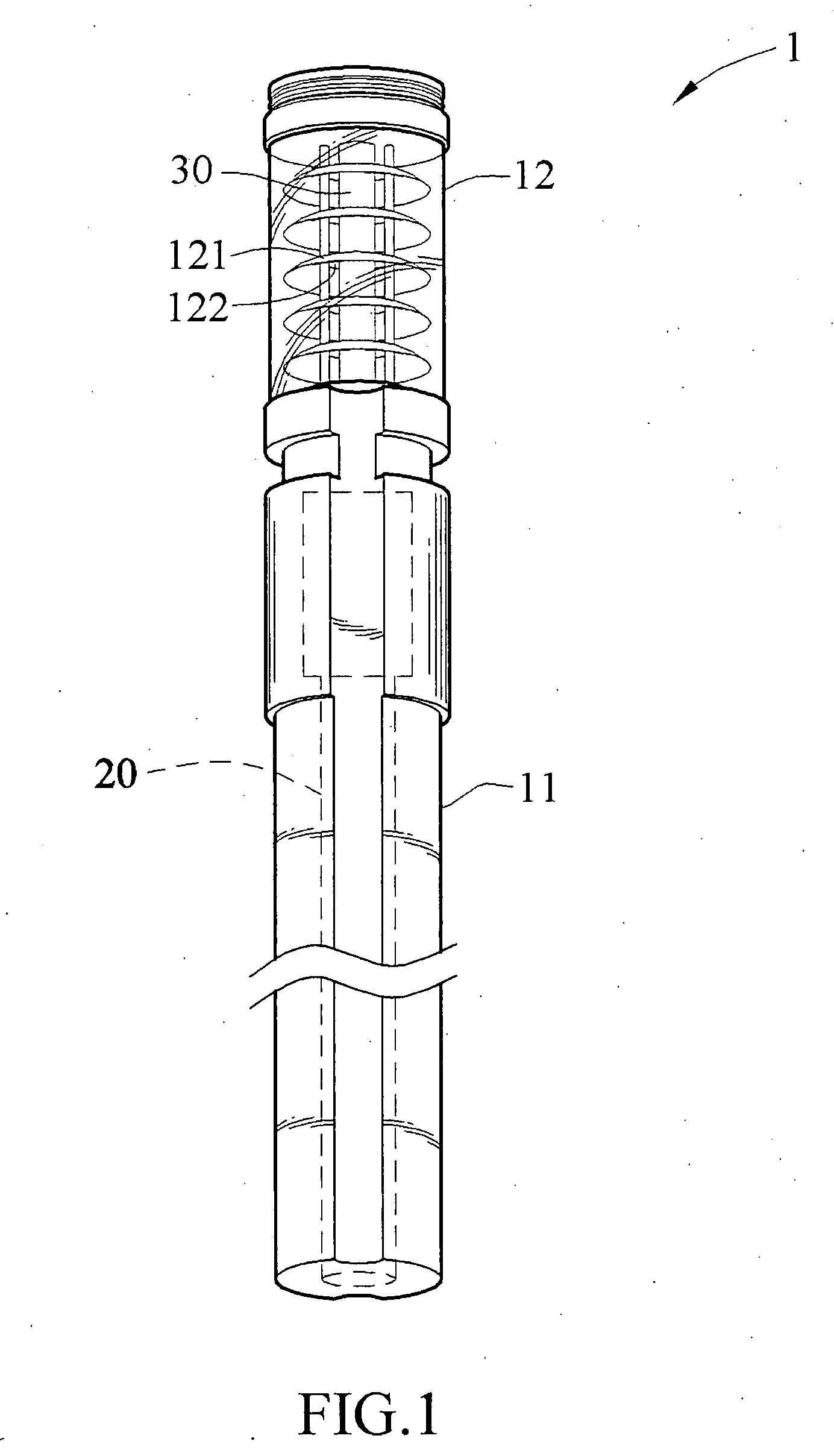
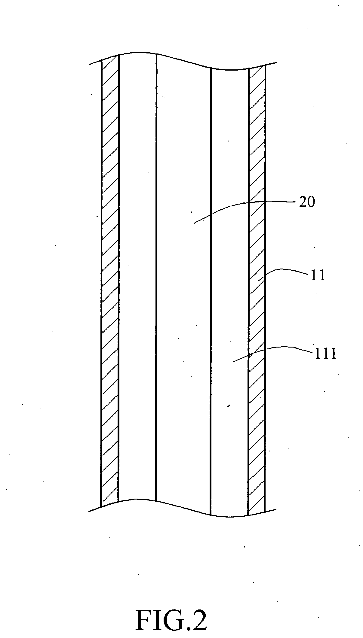
[0019]Firstly, referring to FIGS. 1 and 2, an antenna with a lighting function is disclosed in an embodiment of the present invention that integrates an antenna component with public lighting facilities. The antenna 1 with a lighting function includes an accommodation body 11, a light-transmissive head 12, an antenna component 20, and a light source 30.

[0020]The accommodation body 11 is a non-transparent tube, and has an accommodation space 111 therein for accommodating the antenna component 20. One end of the accommodation body 11 is disposed in the ground, and the other end is used for mounting the light-transmissive head 12. The light-transmissive head 12 is disposed on the accommodation body 11 and allows light to transmit through. The light source 30 is disposed within the light-transmiss...


PUM


Abstract

An antenna with a lighting function includes an accommodation body, a light-transmissive head, a light source, and an antenna component. The accommodation body has an accommodation space therein, and the light-transmissive head is disposed on the accommodation body and allows lights to transmit through. The light source is disposed within the light-transmissive head, and emits a light that is transmitted out of the light-transmissive head. Finally, the antenna component is accommodated within the accommodation body, for transmitting wireless signals and for lighting.

Description

CROSS-REFERENCE TO RELATED APPLICATIONS[0001]This non-provisional application claims priority under 35 U.S.C. § 119(a) on Patent Application No(s). 095210172 filed in Taiwan, R.O.C. on Jun. 9, 2006, the entire contents. of which are hereby incorporated by reference.BACKGROUND OF THE INVENTION[0002]1. Field of the Invention[0003]The present invention relates to an antenna, and more particularly to an antenna capable of protecting an antenna component and having a lighting function.[0004]2. Related Art[0005]With the rapid development and innovation of electronic science and technology, electronics are more and more frequently used by common people in daily life. “Electric” and “magnetic” phenomena occur everywhere in the daily life, besides natural sunlight and lightning, all kinds of electrical appliances, such as televisions, microwaves, lamps, and computers, are electronic products. Furthermore, electromagnetic radio waves of broadcasting stations, TV stations, taxi radios, and sat...

Claims


Application Information

Patent Timeline
IPC IPC(8): G03B15/02
CPCF21S8/088H01Q1/06F21V11/02
Inventor LIN, HSIN-LUNG
Owner SMARTANT TELECOMM
Learn More