
Transmission

a technology of transmission and transmission body, applied in the field of transmission, can solve the problems of increasing manufacturing cost, increasing transmission weight, increasing transmission structure, etc., and achieve the effect of facilitating change and minimizing manufacturing cos

Inactive Publication Date: 2007-12-13
HONDA MOTOR CO LTD
View PDF10 Cites 3 Cited by
  • Summary
  • Abstract
  • Description
  • Claims
  • Application Information

AI Technical Summary

Benefits of technology

[0004]It is an object of the present invention to provide a transmission for which the design can be easily changed when the structure of the transmission is changed, and for which the manufacturing cost can be minimized.
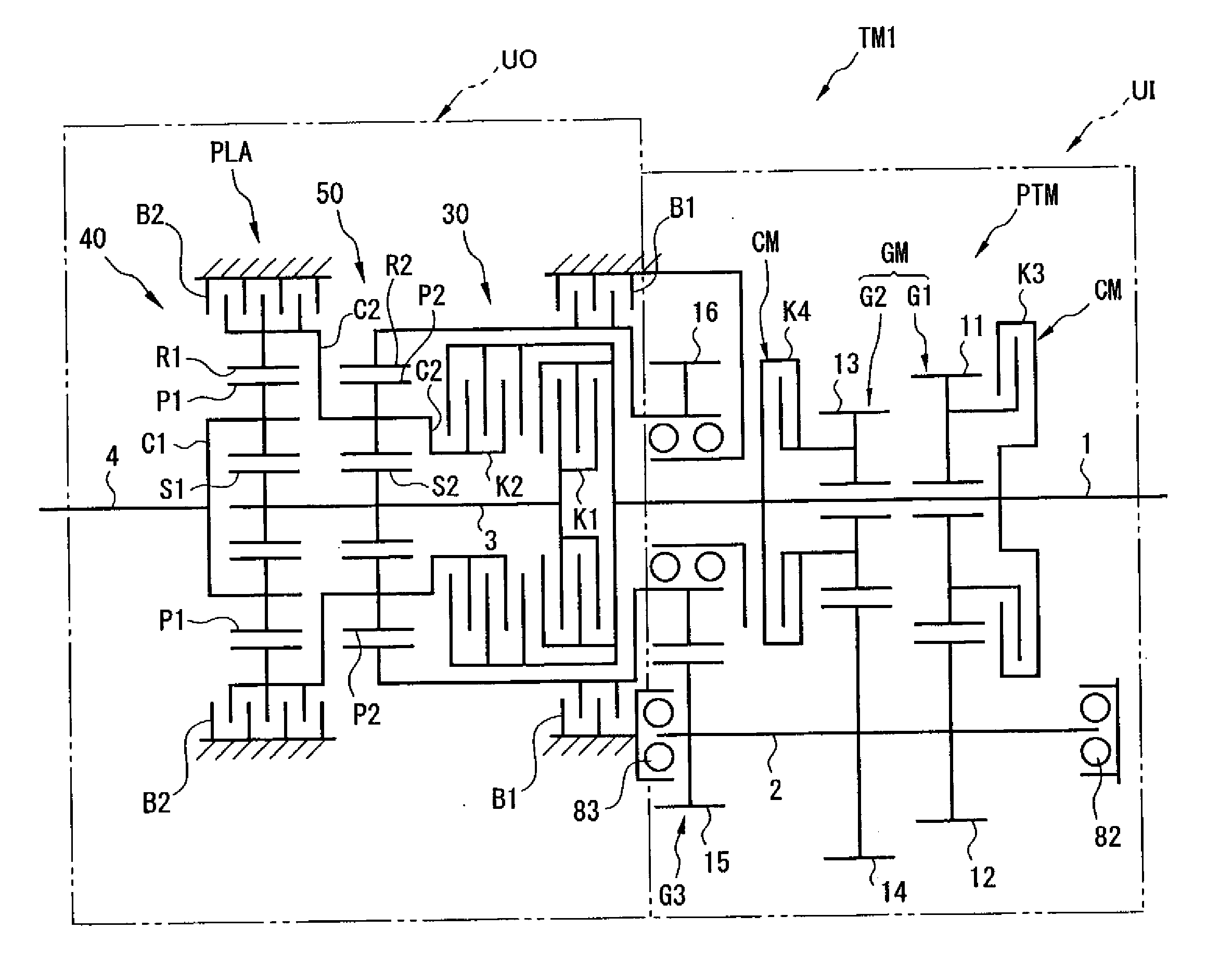
[0010]According to the transmission of the present invention, the transmission includes two units: an upstream side transmission mechanism provided on the upstream side, and a compound planet gear transmission mechanism provided on the downstream side. By modifying the upstream side transmission mechanism without modifying the compound planet gear transmission mechanism on the downstream side, and combining the modified structure with the compound planet gear transmission mechanism, it is possible to increase (or decrease) the number of gear speeds in the transmission. In this way, by making the components of the compound planet gear transmission mechanism in the downstream side of the transmission common, components are made compatible, design changes are easy when changing the structure of the transmission (increasing or decreasing the number of gear speeds), and in particular the manufacturing cost of the transmission can be reduced when increasing the number of gear speeds.
[0011]Also, the compound planet gear transmission mechanism provided on the downstream side is formed by the combination of the first and second planet gear trains, which are single pinion type gear trains with comparatively simple structures. Therefore, it is possible to prevent an increase in size of the transmission mechanism on the downstream side, increase in complexity of the transmission as a whole is prevented, and the manufacturing cost can be reduced.
[0012]Furthermore, the third rotating element has a one way brake that prevents rotation in the direction opposite to the input rotation, but allows rotation in the same direction. Therefore when a torque acts to rotate the output shaft in the opposite direction to the input shaft, the first ring gear that forms part of the third rotating element rotates in the same direction as the first sun gear. In this case, rotation of the first ring gear is not restricted by the one way brake, the first ring gear freely rotates, so power is not transmitted from the input shaft to the output shaft. In this way, by preventing power transmission in the opposite direction to the rotation of the input shaft by the one way brake, it is possible to restrain the reduction in rate of rotation of the output shaft when shifting down. Therefore, it is possible to avoid applying the engine brake when in the first gear speed. Also, using the one way brake, the third rotation element prevents rotation in the opposite direction to the input rotation, and allows rotation in the same direction as the input direction. Therefore it is possible to implement change of gear speeds (in the embodiments, change of gear between the first and second gear speeds) in the embodiments by holding fixed or releasing by the second brake means (in the embodiments, it is not necessary to control the fixing and releasing by the first brake). Therefore, the controllability can be improved.
[0013]Also, by forming the upstream side transmission mechanism with a parallel shaft transmission mechanism, and combining it with the planet gear trains that form the compound type planet gear transmission mechanism on the downstream side, it is possible to increase the number of gear speeds in the transmission with fewer components than the case where the upstream side transmission mechanism is formed with planet gear trains. Therefore it is possible to make the whole transmission lighter (which also results in a reduction in the manufacturing cost of the transmission). Also, by making the upstream side transmission mechanism a parallel shaft transmission mechanism, it is possible to simplify the overall structure of the transmission. By increasing or reducing the number of gear trains in the parallel shaft transmission mechanism (by changing the number of gear trains in the axial direction of the input shaft), it is possible to freely set the number of gear speeds in the transmission.
[0014]In the case where the upstream side transmission mechanism is constituted by a planet gear transmission mechanism, if single pinion type first and second planet gear trains are combined in the same way as in the downstream side planet gear transmission mechanism, it is possible to prevent an increase in the size of the upstream side transmission mechanism compared with the case where a double pinion type planet gear transmission mechanism is used. In addition, it is possible to minimize the torque transmitted to the downstream side transmission mechanism. Therefore, the tangential loads on the gear teeth of the downstream side transmission mechanism can be reduced, and the friction losses can be reduced. If the friction losses can be reduced, the controllability of the transmission is increased.

Problems solved by technology

Therefore, the structure of the transmission becomes more complex.
In particular, there is the problem that as the number of gear speeds increases the weight of the transmission increases, and the manufacturing cost also increases.

Method used


Image

  • Transmission
  • Transmission
  • Transmission

Examples


embodiment 1

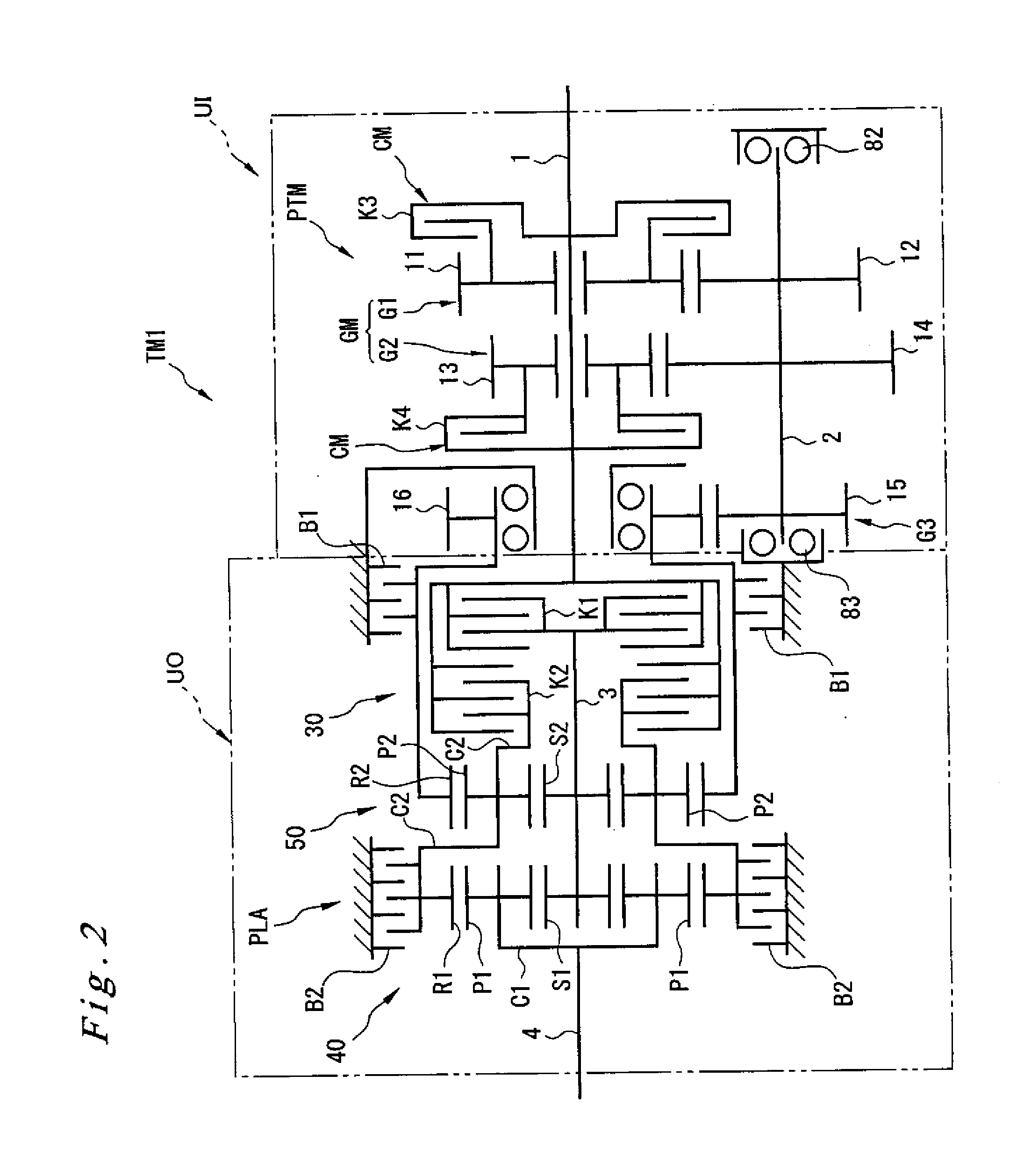
[0035]The following is an explanation of an automatic transmission TM1 according to the first embodiment, with reference to FIGS. 2 and 3.

[0036]As shown in FIG. 2, the automatic transmission TM1 according to the first embodiment includes a parallel shaft type transmission PTM, a compound planet gear train PLA, and planet gear engaging elements 30.

[0037]The input shaft 1 is provided extending from the upstream side to the downstream side within the casing 20, and is rotatably supported on the upstream side by a bearing that is not shown on the drawings. A counter shaft 2 is provided within the casing 20 extending parallel to the input shaft 1. The counter shaft 2 is rotatably supported on the upstream side by a bearing 82, and on the downstream side by a bearing 83. The counter shaft 2 is disposed below the input shaft 1 within the internal space of the casing 20. A center shaft 3 is provided to the downstream side of the input shaft 1 and extends on the same axis as the input shaft ...

embodiment 2

[0063]Next, an automatic transmission TM2 according to a second embodiment is explained with reference to FIGS. 4 and 5. Here, the explanation concentrates on the parts of the structure and function that differ from the automatic transmission TM1 according to the first embodiment. As shown in FIG. 4, the automatic transmission TM2 according to the second embodiment includes a parallel shaft type transmission PTM, a compound type planet gear train PLA, and planet gear engaging elements 30, the same as for the automatic transmission TM1 according to the first embodiment. The compound type planet gear train PLA, and the planet gear engaging elements 30 in the automatic transmission TM2 are the same as for the automatic transmission TM1 according to the first embodiment described above. However, the structure of the parallel shaft type transmission PTM is different.

[0064]As shown in FIG. 4, the parallel shaft type transmission PTM includes an input shaft side gear train GM that includes...

embodiment 3

[0074]Next, an automatic transmission TM3 according to a third embodiment is explained with reference to FIGS. 6 and 7. Here, the explanation concentrates on the parts of the structure and function that differ from the automatic transmission TM1 according to the first embodiment. As shown in FIG. 6, the automatic transmission TM3 according to the third embodiment includes a parallel shaft type transmission PTM, a compound planet gear train PLA, and planet gear engaging elements 30, the same as for the automatic transmission TM1 according to the first embodiment.

[0075]The compound type planet gear train PLA, and the planet gear engaging elements 30 in the automatic transmission TM3 are the same as for the automatic transmission TM1 according to the first embodiment described above, but the structure of the parallel shaft type transmission PTM is different.

[0076]As shown in FIG. 6, the parallel shaft type transmission PTM includes an input shaft side gear train GM that includes a firs...


PUM


Abstract

The present invention includes an input side transmission unit that transforms the rotation of the input shaft that rotates by receiving input rotation into N steps, and transmits the transformed rotation to the counter shaft; and an output side transmission unit that includes a first planet gear train and a second planet gear train, and that transforms the rotation of the counter shaft and outputs the transformed rotation to the output shaft. Of the first through fourth rotating elements constituting the output side transmission unit, the first and second sun gears are connected so that they can be freely engaged with or disengaged from the input shaft via the first clutch; the first carrier is connected to the output shaft; the second carrier and the first ring gear are connected so that they can be freely engaged with or disengaged from the input shaft via the second clutch and can be held fixed by the second brake; and the second ring gear can be held fixed by the first brake, and is connected to the upstream side output member.

Description

FIELD OF THE INVENTION[0001]The present invention relates to a transmission which is constituted to have a planet gear train, and which transforms the speed of rotation of the input shaft and outputs it to the output shaft.BACKGROUND OF THE INVENTION[0002]There is a trend towards increasing the number of gear speeds in transmissions used in vehicles, as a result of requirements to improve the fuel consumption and acceleration performance (for example, see Japanese Patent Application Laid-open No. 2000-266138). In this type of transmission, the number of gear speeds is increased by providing a plurality of planet gear trains.[0003]However, if the number of gear speeds is increased, the number of meshing elements is increased accordingly. Therefore, the structure of the transmission becomes more complex. In particular, there is the problem that as the number of gear speeds increases the weight of the transmission increases, and the manufacturing cost also increases.SUMMARY OF THE INVE...

Claims


Application Information

Patent Timeline
Patent Type & Authority Applications(United States)
IPC IPC(8): F16H37/02
CPCF16H3/663F16H2200/006F16H2200/0086F16H2200/0013F16H2200/2012F16H2200/2046F16H2200/2097F16H2200/2007
Inventor SUGINO, SOICHITAKAHASHI, TSUKASASAWA, YASUHIRO
Owner HONDA MOTOR CO LTD
Learn More