

Two speed gearbox
a two-speed gearbox and gearbox technology, applied in the field of gearboxes, can solve the problems of large transmission and bearing design, unfavorable influencing the service life and reliability of the 2-speed gearbox, and increased wear and heat buildup
- Summary
- Abstract
- Description
- Claims
- Application Information
AI Technical Summary
Benefits of technology
Problems solved by technology
Method used
Image

Examples
Embodiment Construction
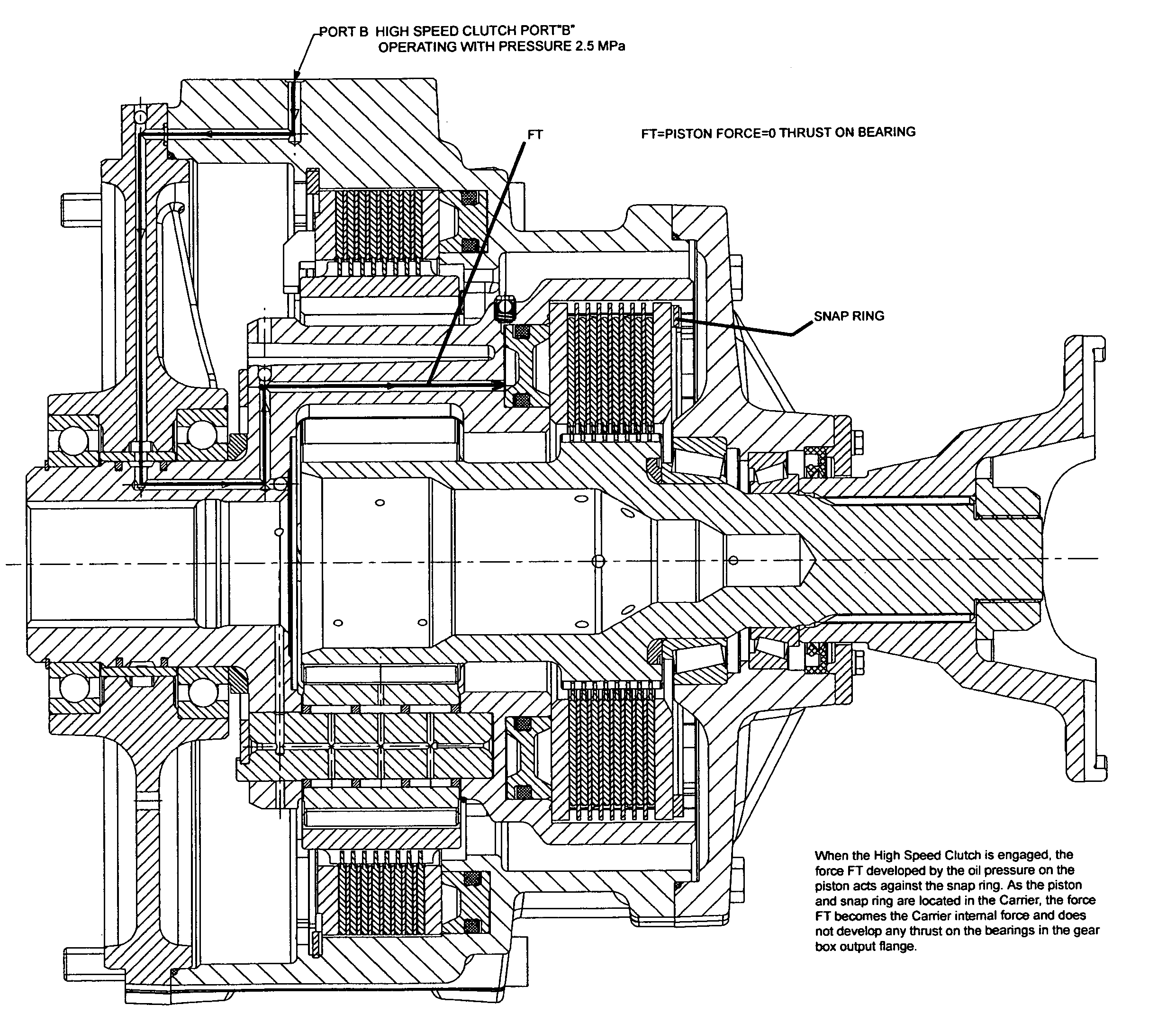
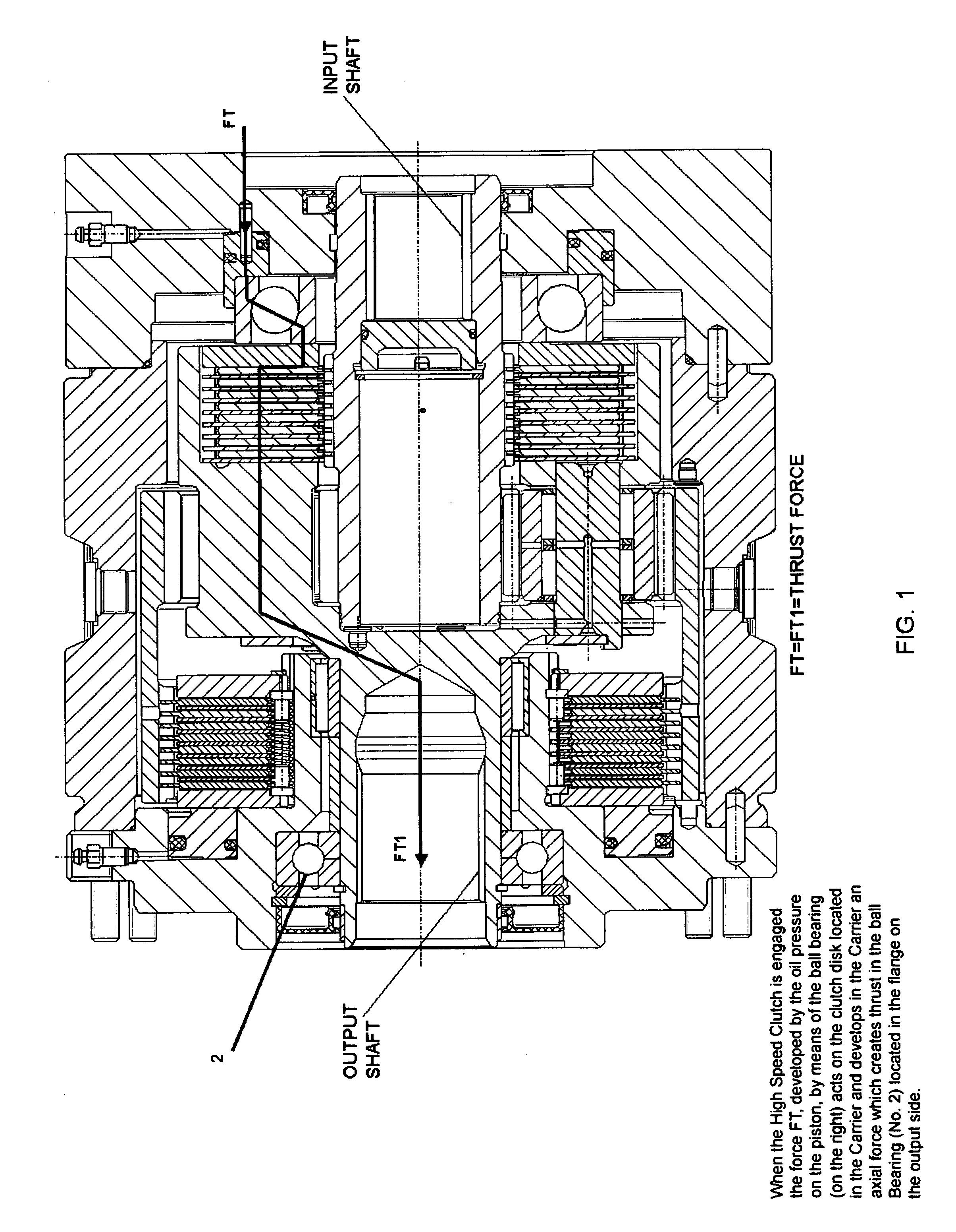
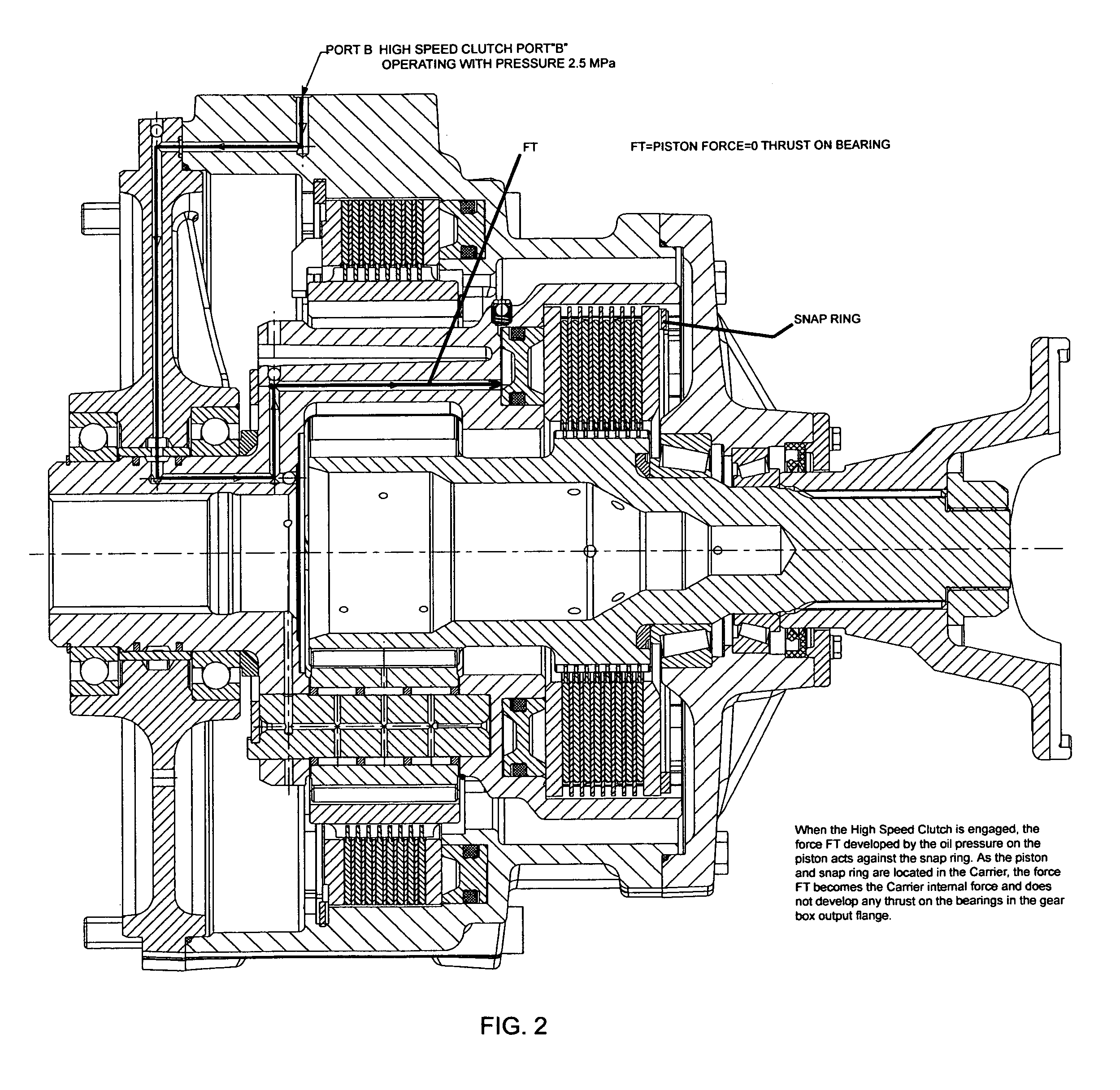
[0041]FIG. 3 is side cross sectional view of an assembled preferred embodiment of the two speed gearbox of the present invention. The two speed gearbox is for use with any device that receives a torque input and provides a torque output usually under high speeds and high temperature operating conditions. The following is the list of parts of the preferred embodiment shown in FIG. 3:[0042]1) Gear Housing[0043]2) Flange Front[0044]3) Flange Back[0045]4) Planet Carrier[0046]5) Planet Sun Gear[0047]6) Planet Ring Gear[0048]7) Planet Gears[0049]8) Planet Pins[0050]9) High Speed Clutch (Pack with static discs 9a, rotating friction discs 9b)[0051]10) High Speed Clutch Piston (Pack)[0052]11) High Speed Clutch Dynamic Seal[0053]12) High Speed Clutch Dynamic Seal Bushing[0054]13) Low Speed Clutch (Pack-Static with static discs 13a, static friction discs 13b)[0055]14) Low Speed Clutch Piston (Pack)[0056]15) Driveline Yoke[0057]16) Flange Front Hydrostatic Input[0058]17) Snap Ring[0059]18) Cent...
PUM
 Abstract
Description
Claims
Application Information