Bone Screw

Active Publication Date: 2007-12-13
AESCULAP AG
View PDF19 Cites 32 Cited by
  • Summary
  • Abstract
  • Description
  • Claims
  • Application Information

AI Technical Summary

Benefits of technology

[0038] In order to facilitate the assembly of the bone screw and, in particular, to make instruments for the assembly of the bone screw superfluous, it is advantageous when a slide-on surface adjoins the third or the fourth snap-in element, the respectively other snap-in element being able to slide on this surface during the insertion of the securing element into the securing element receiving means. For example, the slide-on surface can extend in a distal direction starting from the third snap-in element arranged on the securing element so that the fourth snap-in element arranged on the head of the bone screw can slide onto it during the insertion of the securing element into the securing element receiving means and, as a result, be moved outwards in a radial direction until it engages behind the third snap-in element, whereby it can be moved again in a radial direction towards the longitudinal axis. The securing element can, therefore, be secured in the securing element receiving means in this way.
[0039] The stability of the bone screw may be increased when the securing element is designed in the shape of a set bolt with a bolt shaft and a bolt head.
[0040] The construction of the securing element is particularly simple when the bolt shaft forms the securing element section which is designed in the shape of an external polyhedron.
[004

Problems solved by technology

This has the disadvantage that a securing element must be provided at every opening in the bone plate.
If, however, not all the bone screw receiving means of the bone plate are required, the securing elements arranged at the bone screw receiving means whic

Method used


Image

  • Bone Screw
  • Bone Screw
  • Bone Screw

Examples


first embodiment

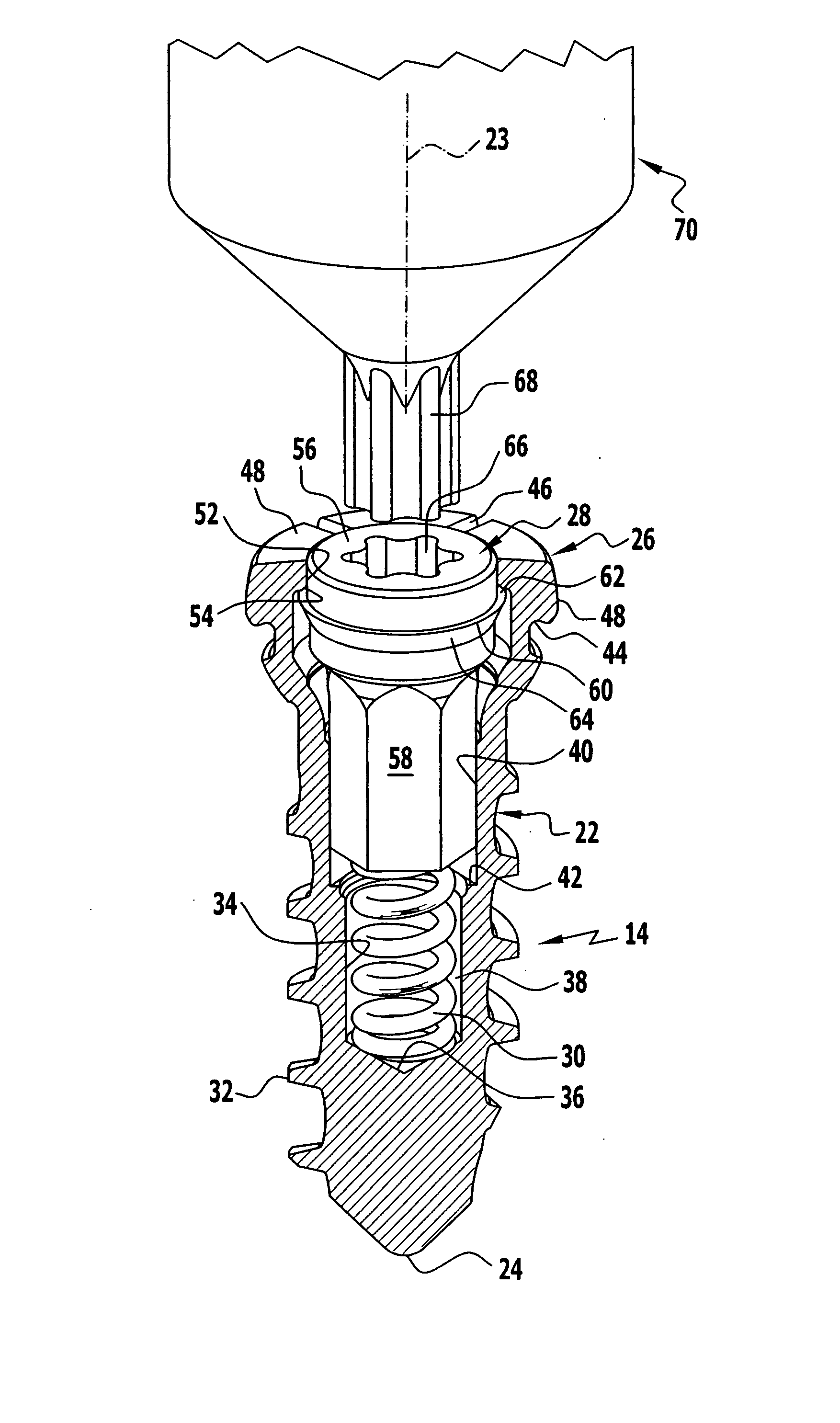
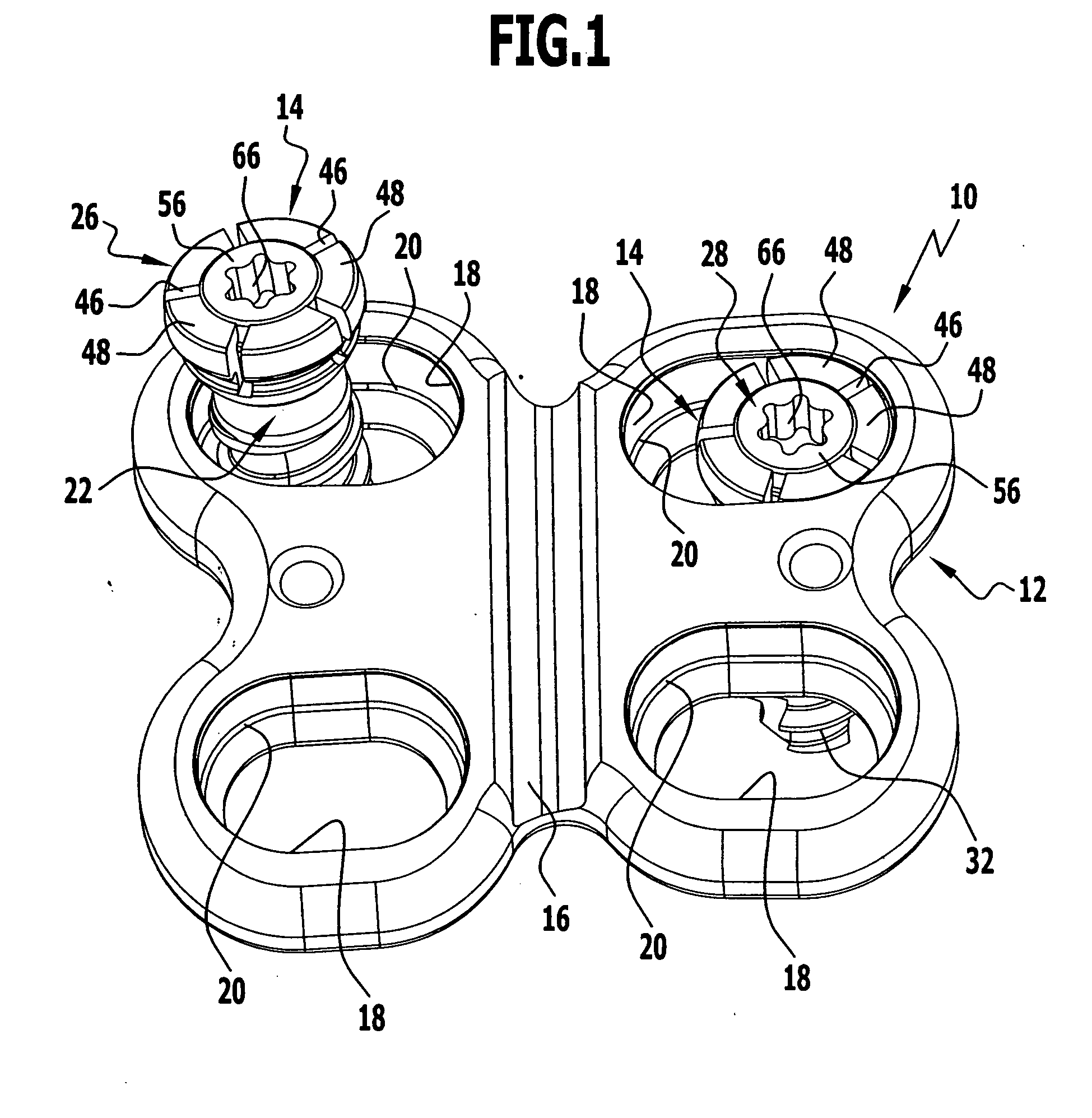
[0059] The bone screws 14, which, in the form of a first embodiment, will be explained in greater detail in the following in conjunction with FIGS. 1 to 5, serve to secure the bone plate 12 on bone parts which are not illustrated.

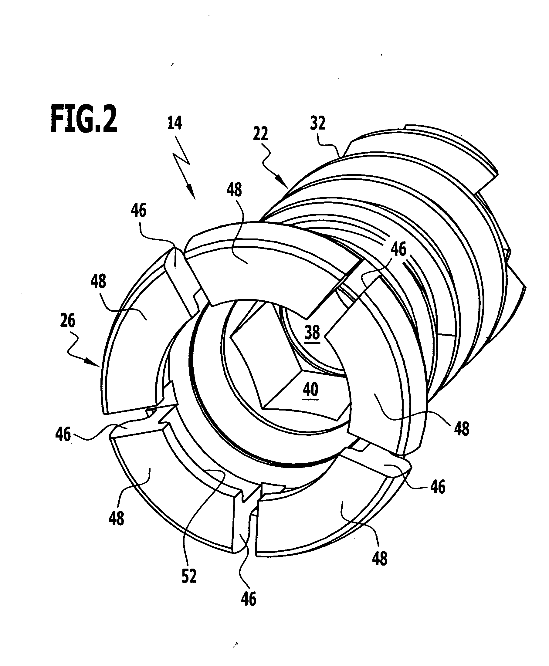
[0060] The bone screw 14 is essentially designed in three parts. It comprises a shaft 22, which defines a longitudinal axis 23, a screw tip 24 on the distal side and a screw head 26 on the proximal side, as well as a securing element in the form of a locking pin 28 and a helical spring 30 serving as a holding element. The shaft 22 is provided over approximately three quarters of its length, starting from its screw tip 24, with an external thread 32 which is preferably designed to be self-cutting. An outer contour or cover end of the screw head 26 is essentially of a cap-like design and adapted to the recessed area of the opening 18 formed by the inner edge 20, whereby a polyaxial adaptation of the screw head 26 in the recessed opening 18 is made possible.

[...

second embodiment

[0071] In FIG. 6, a bone screw provided altogether with the reference numeral 14′ is illustrated. The bone screw 14′ differs from the bone screw 14 illustrated in FIGS. 1 to 5 in that instead of the helical spring 30 a stack 74′ of plate springs comprising altogether elf plate springs 72′ is provided which is supported on the base 36′ on the distal side and on the distal end of the bolt shaft 58′ on the proximal side. All the remaining parts and elements of the bone screw 14′ correspond to those of the bone screw 14 and so the same parts are also provided with the same reference numerals but with a superior case prime (′) added in FIG. 6. The mode of operation of the bone screw 14′ corresponds completely to that of the bone screw 14 described in conjunction with FIGS. 1 to 5.

third embodiment

[0072] a bone screw provided altogether with the reference numeral 14″ is illustrated in FIG. 7. Instead of the helical spring 30 of the bone screw 14, a holding member 76″ is provided for the bone screw 14″. All the other parts and elements of the bone screw 14″ correspond to those of the bone screw 14 and so identical reference numerals are used but with a double prime (″) added.

[0073] The holding member 76″ is variable in its volume in the embodiment illustrated. For this purpose, it has a sleeve which surrounds an element which is variable in expansion or shape and is produced from a memory metal. As a result of changes in temperature at the bone screw, the element expands or contracts so that the locking pin 28″ can be transferred from the non-securing position illustrated in FIG. 7 into the securing position, in which the stop surfaces 54″ and 62″ abut on one another.


PUM


Abstract

In order to improve a bone screw with a shaft defining a longitudinal axis and with a head which can be brought into engagement with a bone screw receiving means of a bone plate for the releasable connection of the bone screw to the bone plate, wherein a securing element for securing a connection between the bone screw and the bone plate is provided, wherein the bone screw can be brought from a position of engagement, in which the bone screw is held on the bone plate, into a release position, in which the bone screw can be released from the bone plate, wherein the securing element can be brought from a non-securing position, in which the bone screw can be brought into the release position, into a securing position for securing the connection between the bone screw and the bone plate, in which the bone screw takes up the position of engagement, such that a bone plate can be fixed to bone parts more easily and more securely it is suggested that the securing element be supported on the bone screw so as to be movable.

Description

[0001] Pursuant to 35 U.S.C. §365(c), this application is a continuation application of International Patent Application number PCT / EP2005 / 010759 filed on Oct. 6, 2005 and desginating the United States, which claims priority to the content of German application number 10 2004 050 040, filed Oct. 8, 2004, which is incorporated herein by reference in their entirety and for all purposes.BACKGROUND OF THE INVENTION [0002] The present invention relates to a bone screw with a shaft defining a longitudinal axis and with a head which can be brought into engagement with a bone screw receiving means of a bone plate for the releasable connection of the bone screw to the bone plate, wherein a securing element is provided for securing a connection between the bone screw and the bone plate, wherein the bone screw can be brought from a position of engagement, in which the bone screw is held on the bone plate, into a release position, in which the bone screw can be released from the bone plate, whe...

Claims


Application Information

Patent Timeline
IPC IPC(8): A61B17/58
CPCA61B17/8038A61B17/864A61B2017/00867A61B2017/00539A61B2017/00557A61B17/8685
Inventor PEUKERT, ANDREABEGER, JENSHAAS, ALEXANDER
Owner AESCULAP AG
Why Eureka
Try Eureka