Dust collector of vacuum cleaner
a technology of dust collector and vacuum cleaner, which is applied in the direction of filtration separation, cleaning filter means, and separation processes, etc., can solve the problems of air not ascending any more, dust-collection efficiency of dust collectors deteriorating to some extent, etc., and achieves improved dust-collection efficiency of dust collectors, reduced flow rate of air, and substantial reduction of pressure loss
- Summary
- Abstract
- Description
- Claims
- Application Information
AI Technical Summary
Benefits of technology
Problems solved by technology
Method used
Image

Examples
first embodiment
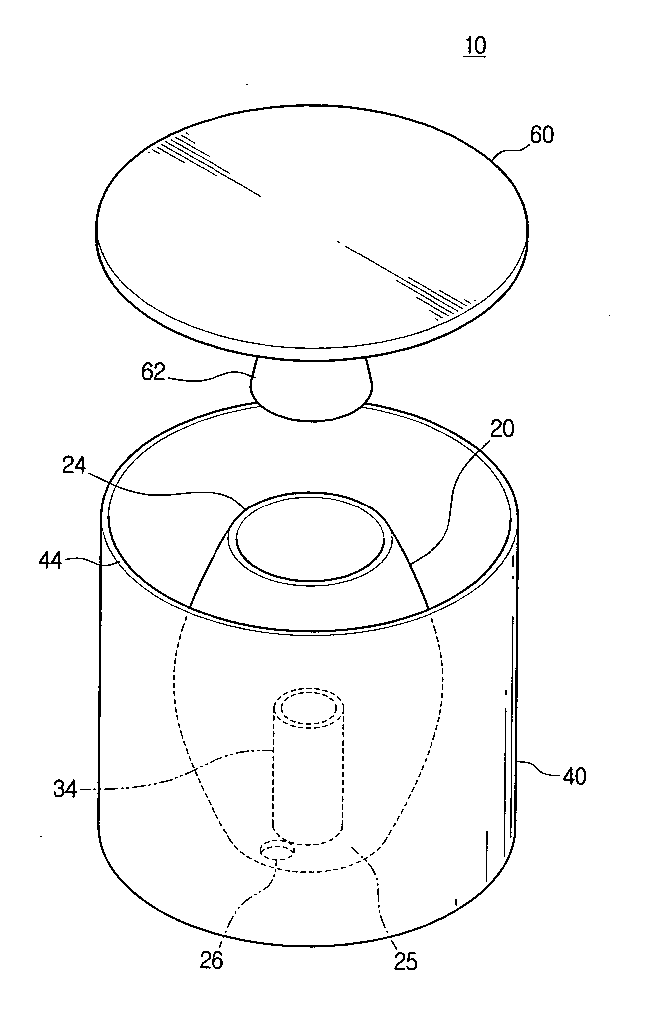
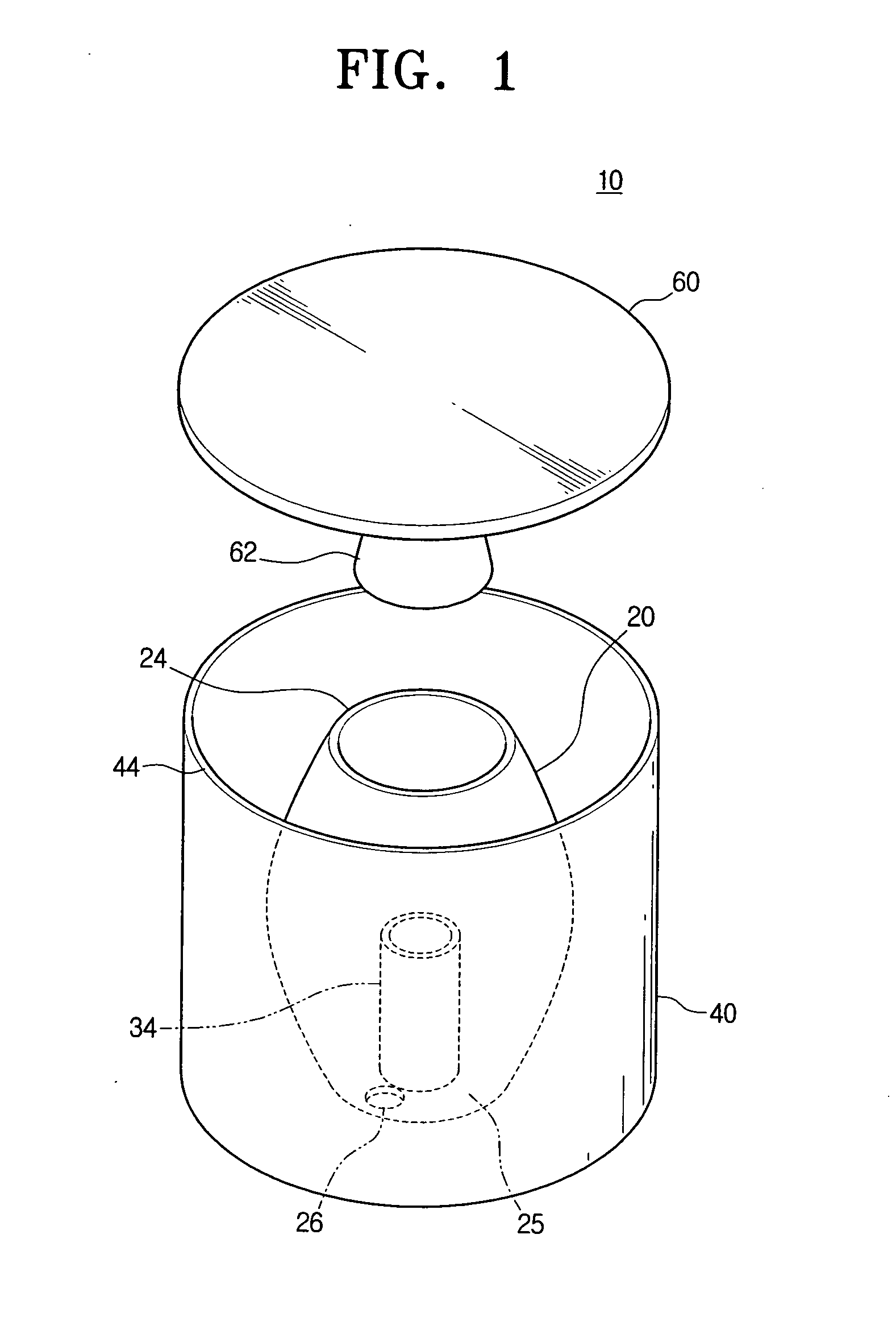
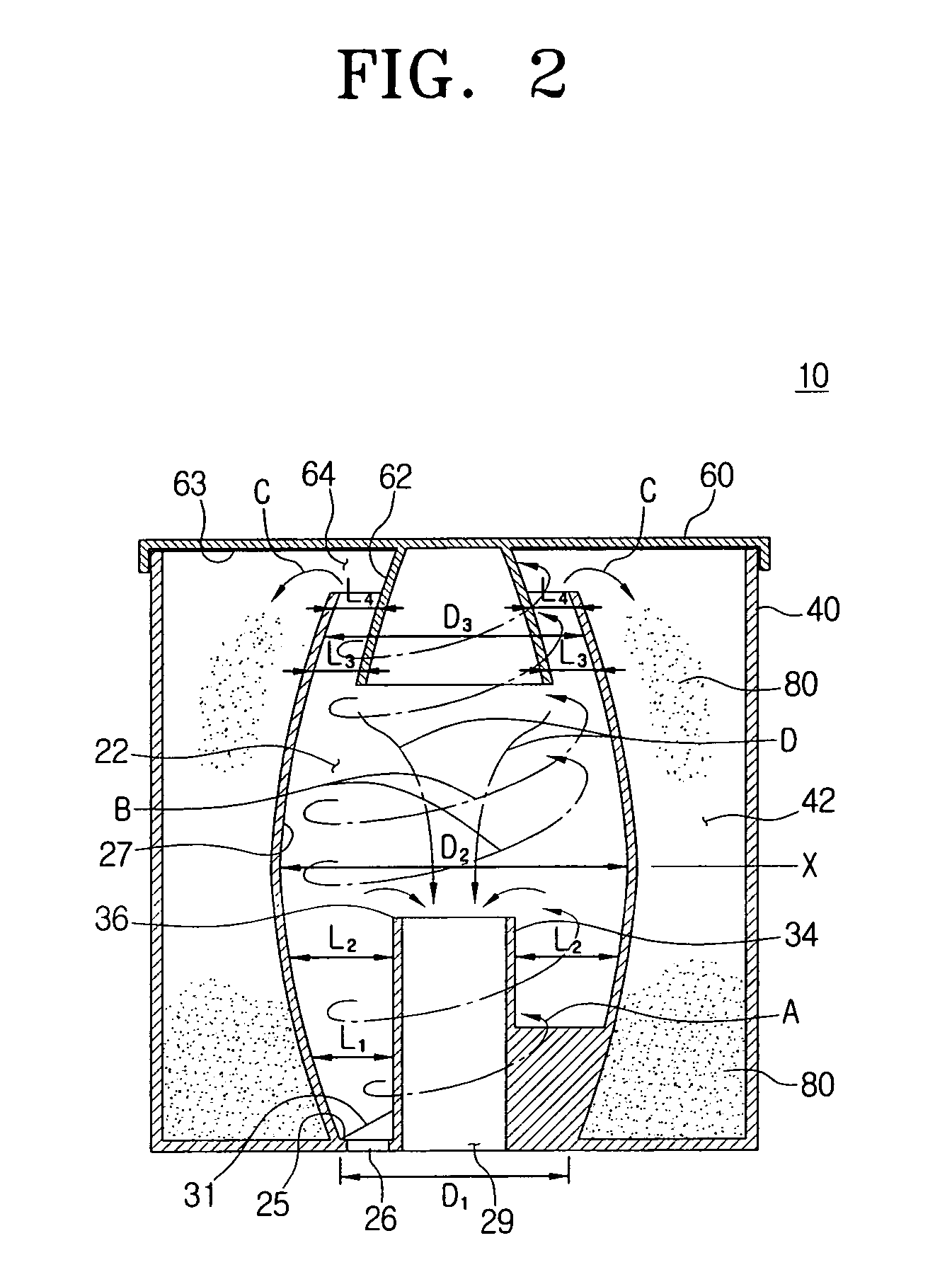
[0027]Referring to FIGS. 1 and 2, the dust collector 10 of a vacuum cleaner according to the present disclosure comprises a cyclone body 20, a dust-bin body 40, and a cover member 60.
[0028]The cyclone body 20 is formed in a barrel shape, the inside of which forms a cyclone clamber 22, into which air is admitted in such a manner as to rotate, wherein the cyclone body 20 includes an air inlet 26, an outlet pipe 34, and a helical guide 31. The air inlet 26 is formed through a side part of the bottom wall of the cyclone body 20. The outlet pipe 34, through which air is discharged, also extends vertically upward from the bottom wall of the cyclone body 20. The air inlet 26 is connected to a suction brush (not shown) of a vacuum cleaner (not shown) in such a manner as to serve as a passage, through which air containing dust or dirt is admitted into the cyclone chamber 22.
[0029]Although the air inlet 26 is formed through the bottom wall of the cyclone body 20 in the present embodiment, it ...
third embodiment
[0038]FIG. 4 is a cross-sectional view of the dust collector 310. In the present embodiment, the cyclone body 320 comprises, with reference to the X-axis, a lower side wall 320a in a bowl shape, the inner diameter of which is gradually increased as approaching the top end thereof, and an upper side wall 320b in a cylindrical shape vertically extending from the top end of the lower side wall 320a. Therefore, the inner diameter of the cyclone body 320 is increased as approaching the X-axis near the top end of the outlet pipe 334 from the bottom end of the cyclone body 320 and then retained constant above the X-axis. The rotation guide member 362 is also formed in a hollow shape, the inner diameter of which is retained constant, and vertically depends from the bottom surface of the cover member 360. Because the other components are identical to those of the above-mentioned embodiments, detailed description thereof is omitted.
fourth embodiment
[0039]FIG. 5 is a cross-sectional view of the dust collector 410. In the present disclosure, the cyclone body 420 comprises, with reference to the X-axis, a lower side wall in an inverted truncated cone shape, the inner diameter of which is reduced as approaching the bottom end thereof, and an upper side wall in a cylindrical shape vertically extending from the top end of the lower part 420b. Therefore, the inner diameter of the cyclone body 420 is increased as approaching the X-axis near the top end of the outlet pipe 434 from the bottom end of the cyclone body 420 and then retained constant to the top end of the cyclone body 420. The rotation guide member 462 is also formed in a hollow shape, the inner diameter of which is retained constant, and vertically depends from the bottom surface of the cover member 460. Because the other components are identical to those of the above-mentioned embodiments, detailed description thereof is omitted.
[0040]In the third and fourth embodiments, ...
PUM
| Property | Measurement | Unit |
|---|---|---|
| Diameter | aaaaa | aaaaa |
Abstract
Description
Claims
Application Information
 - R&D
- Intellectual Property
- Life Sciences
- Materials
- Tech Scout
- Unparalleled Data Quality
- Higher Quality Content
- 60% Fewer Hallucinations
Browse by: Latest US Patents, China's latest patents, Technical Efficacy Thesaurus, Application Domain, Technology Topic, Popular Technical Reports.
© 2025 PatSnap. All rights reserved.Legal|Privacy policy|Modern Slavery Act Transparency Statement|Sitemap|About US| Contact US: help@patsnap.com