Hoisting-Cable Drive Comprising a Single Bottom-Hook Block and Two Winches

a technology of hoisting cable and bottom-hook block, which is applied in the direction of hoisting equipment, load-engaging elements, transportation and packaging, etc., can solve the problems of difficult handling and high rigidity

Active Publication Date: 2007-12-20
TADANO DEMAG GMBH
View PDF3 Cites 30 Cited by
  • Summary
  • Abstract
  • Description
  • Claims
  • Application Information

AI Technical Summary

Benefits of technology

[0021] As already mentioned, the registering device can be a simple limit switch which detects a maximum permissible kinematic change in the state of the force equilibrium device, such as for example a maximum permissible twisting, and transmits this information to the winch synchronisation control system.
[0022] According to a further aspect of the hoisting-cable drive according to the invention, said hoisting-cable drive comprises a winch synchronisation control system which, for example by processing the signals of the limit switch or generally by processing the registered kinematic change in state, adjusts the rotary speed of at least one of the two hoisting winches so that the length of both cable lines between the boom head and the single bottom-hook block is essentially always kept the same. Providing the hoisting-cable drive with a registering device and with a winch synchronisation control system is thus advantageous in that, in contrast to the known solution comprising a double bottom-hook block, wherein there is no longer a danger that due to excessively different elongation of one cable line the bottom-hook block twists excessively, which can lead to overload of the other cable line.

Problems solved by technology

In contrast to a known double bottom-hook block, it is thus not necessary for the two separate sheave sets of the double bottom-hook block to comprise a complex mechanical load equalisation device which, as already mentioned above, is very solid and difficult to handle.

Method used


Image

  • Hoisting-Cable Drive Comprising a Single Bottom-Hook Block and Two Winches
  • Hoisting-Cable Drive Comprising a Single Bottom-Hook Block and Two Winches
  • Hoisting-Cable Drive Comprising a Single Bottom-Hook Block and Two Winches

Examples


Embodiment Construction

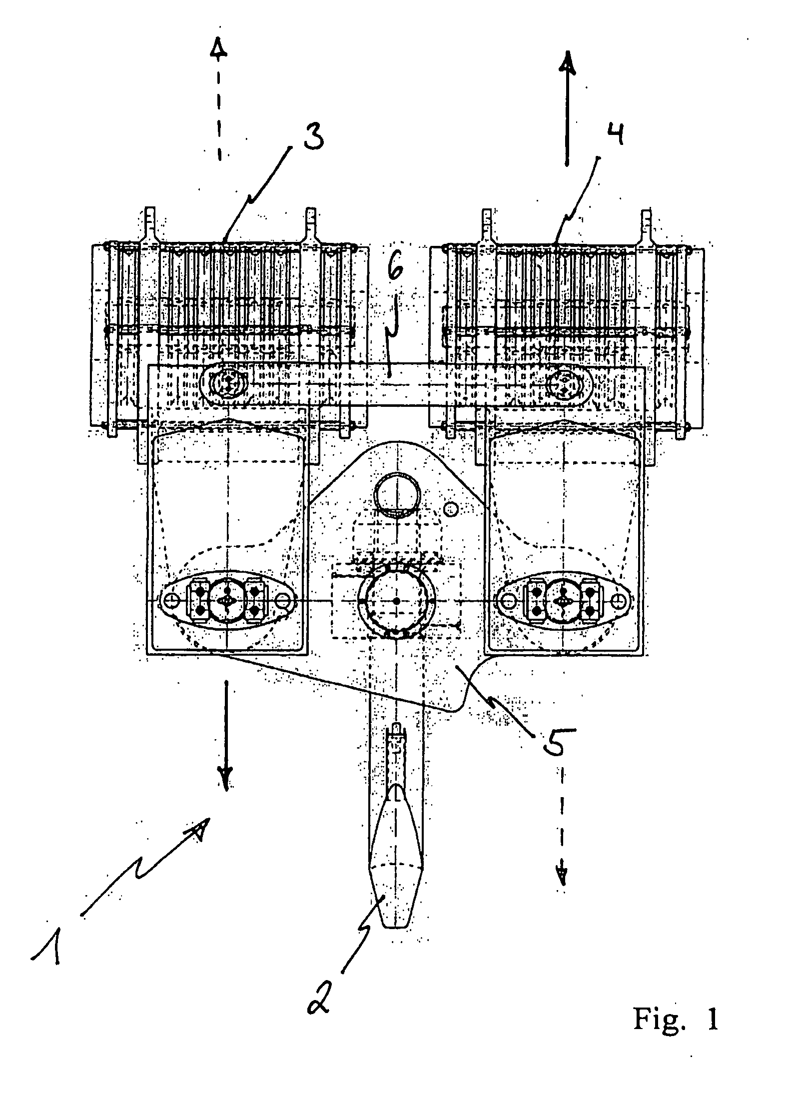
[0065]FIG. 1 shows a front view of a known double bottom-hook block 1. The double bottom-hook block 1, which is a snatch block comprising a hook 2, essentially comprises two sheave sets 2, 4, each of which in turn comprises several pulleys. The two sheave sets 3, 4 are mutually connected, so as to hinge, to two pairs of cross arms 5, 6 such that the two sheave sets 3, 4 are in a position to slide relative and parallel to each other in their mutual height position, as indicated by the arrows. As shown in FIG. 1, the construction of such a double bottom-hook block 1 is very complex. Due to the considerable loads that have to be transmitted by the cross arms 6, 5, said cross arms 6, 5 have to be designed so as to be very resistant, as shown in the diagram in particular by the solid design of the lower cross arm 5, thus resulting in enormous component dimensions and thus in considerable overall size of the double bottom-hook block. However, such an enormous design height of the double b...


PUM


Abstract

The invention proposes a hoisting-cable drive for a mobile crane, which hoisting-cable drive uses a single bottom-hook block (15) instead of a known double bottom-hook block. However, to prevent this single bottom-hook block (15) from tilting in the two cable lines (9, 10), for example due to possible variations in the elongation of the two cable drives, the hoisting-cable drive according to the invention comprises a kinematic force equilibrium device (17, 21), which can equalize such differences. To this effect, another embodiment of the hoisting-cable drive according to the invention uses a hoisting-cable load pickup (21) within each cable line arrangement so that the rotary speed of the winches (7, 8) can be varied, taking into account any load differences in the individual hoisting-cable lines (9, 10). Furthermore, the invention also proposes that the rotary speed of the winches (7, 8) be adjusted, taking into account the geometric winch states and crane states.

Description

TECHNICAL FIELD [0001] The present invention generally relates to the technical and constructional design of a hoisting-cable drive for a crane, and in particular a hoisting-cable drive comprising at least two hoisting winches, which hoisting-cable drive is suitable for raising or lowering a single bottom-hook block by means of two mechanically non-synchronised separate hoisting-cable winches without there being any danger synchronised or of tilting. Furthermore, the invention relates to a mobile crane equipped with the hoisting-cable drive according to the invention. [0002] Furthermore, the present invention relates to a winch control system for a cable drive, comprising at least two mechanically non-synchronised hoisting winches, which winch control system is suitable for operating the cable drive such that the two sheave sets which form part of the cable drive do not tilt in relation to each other for example as a result of different elongation of the individual cable lines. [000...

Claims


Application Information

Patent Timeline
Patent Type & Authority Applications(United States)
IPC IPC(8): B66D3/20
CPCB66C13/18B66D1/54B66D1/26
Inventor NOESKE, INGOWECKBECKER, ALFONSBECKMANN, AXEL
Owner TADANO DEMAG GMBH
Why Eureka
Try Eureka