Photovoltaic system and method for operating a photovoltaic system

a photovoltaic system and photovoltaic technology, applied in the field of photovoltaic systems, can solve the problems of high system cost and the tendency of capacitors in the system to produce a sluggish response to changes in operating conditions, and achieve the effects of reducing maintenance costs, increasing service life, and long service li

Inactive Publication Date: 2007-12-20
ADENSIS
View PDF11 Cites 180 Cited by
  • Summary
  • Abstract
  • Description
  • Claims
  • Application Information

AI Technical Summary

Benefits of technology

[0021]The afore-described photovoltaic system has a long service life.
[0022]It has been confirmed through experimentation that the system achieves quickly, usually within several seconds, peak power (MPP). The system automatically adjusts to the new operating point in response to a change of external parameters, such as temperature, incident solar radiation intensity or changes in the AC power grid while retaining the aforementioned advantages: The system employs only a single electromechanical conversion device, consisting of the DC motor, the AC voltage generator, and a shaft connecting the motor and the generator. This reduces maintenance costs, and with appropriate care also increases the service life, compared to a system with a large number of electric converters / inverters. Converter units of this type are presently commercially available for a power of up to 2.5 MW.

Problems solved by technology

However, these systems tend to be expensive.
Although electric converters / inverters have a high power conversion efficiency, the capacitors in the system tend to produce a sluggish response to changes in the operating conditions.
However, this application only addresses the mechanical characteristic of the motor-generator combination and proposes to arrange several pole wheels on a shaft, with each pole wheel operating inside their own stator.

Method used


Image

  • Photovoltaic system and method for operating a photovoltaic system
  • Photovoltaic system and method for operating a photovoltaic system
  • Photovoltaic system and method for operating a photovoltaic system

Examples


Embodiment Construction

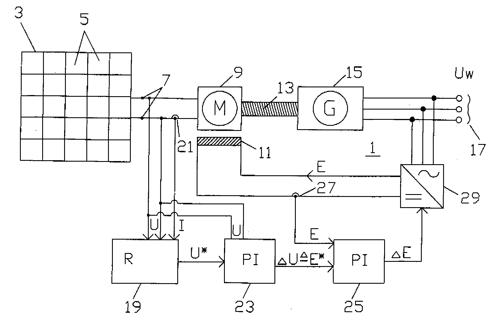
[0028]Throughout all the Figures, same or corresponding elements may generally be indicated by same reference numerals. These depicted embodiments are to be understood as illustrative of the invention and not as limiting in any way. It should also be understood that the figures are not necessarily to scale and that the embodiments are sometimes illustrated by graphic symbols, phantom lines, diagrammatic representations and fragmentary views. In certain instances, details which are not necessary for an understanding of the present invention or which render other details difficult to perceive may have been omitted.

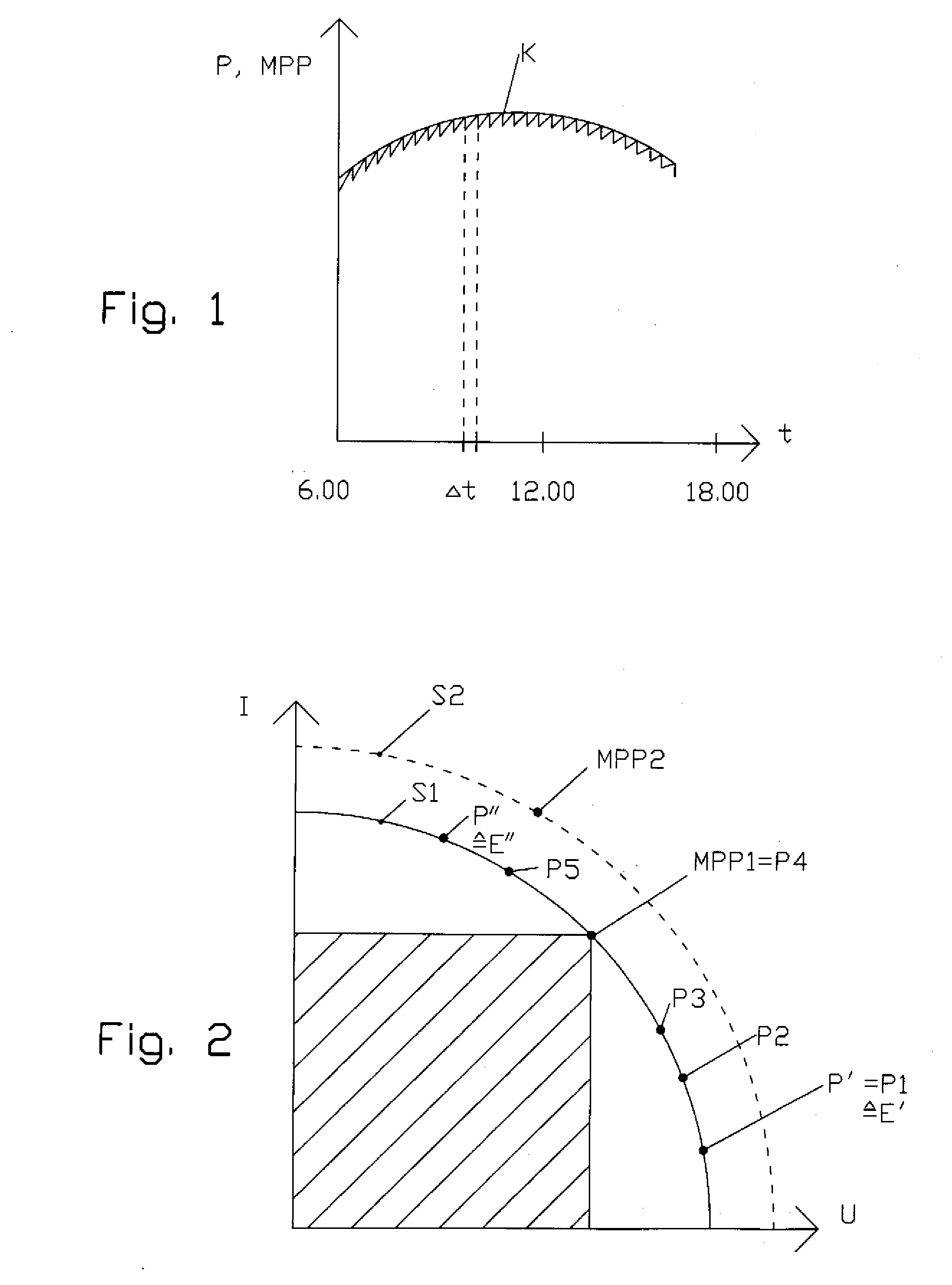
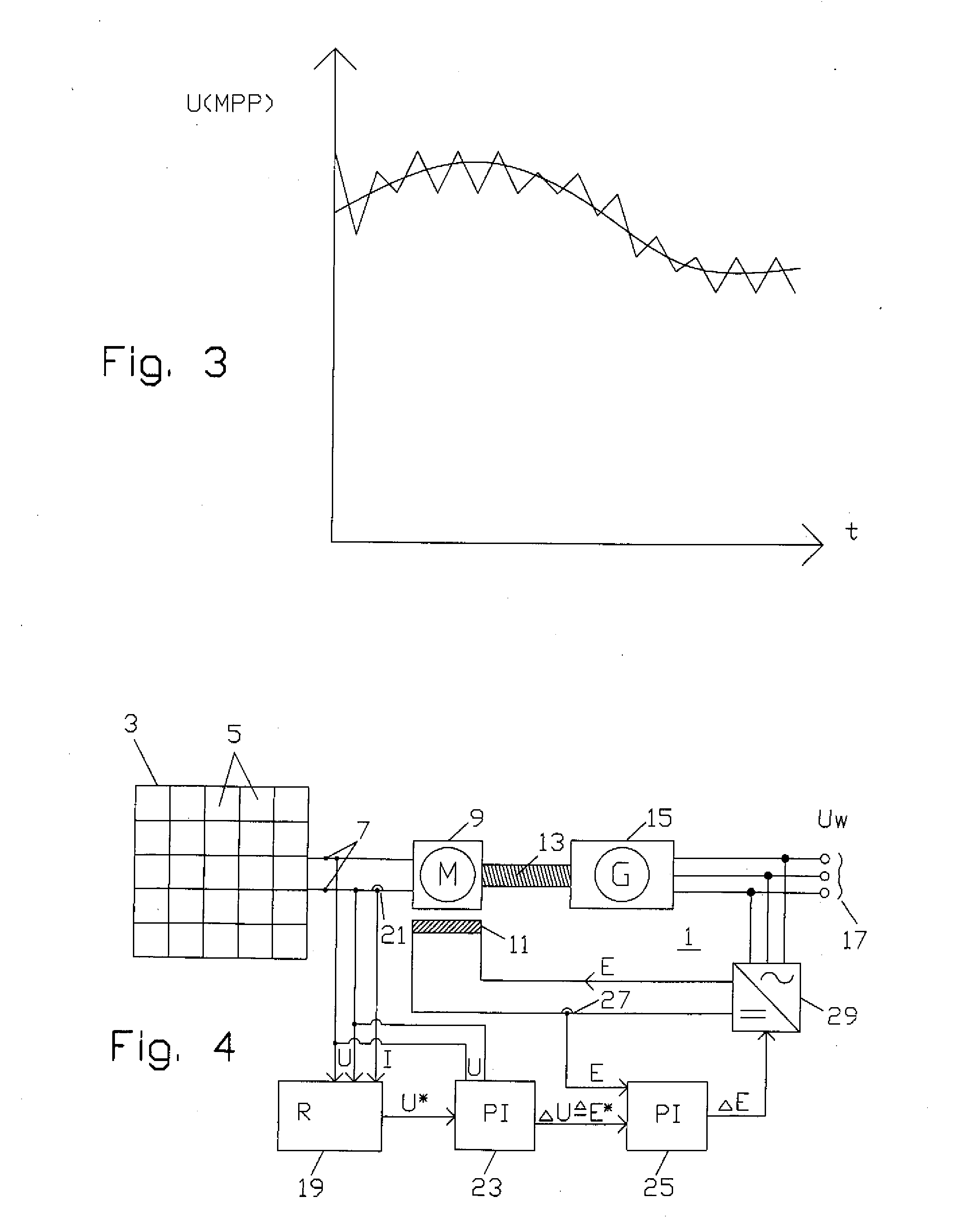
[0029]Turning now to the drawing, and in particular to FIG. 1, there is depicted as a continuous curve K the peak power MPP (peak power point) that a photovoltaic system can supply over the course of one day, indicated by time t, between 6 a.m. and 6 p.m. It will be assumed that there are no clouds or no large temperature changes occur.

[0030]According to the proposed exempla...


PUM


Abstract

A photovoltaic system includes a plurality of photovoltaic modules and a DC motor connected to a three-phase generator driven by a shaft. The three-phase generator is connected to a power mains. The electric power supplied to the DC motor by the plurality of photovoltaic modules is repeatedly measured and adjusted, by changing an external excitation current of the DC motor, to the peak power attainable at the current ambient temperature and the current incident solar radiation intensity. The peak power is preferably determined by incrementally changing the excitation current in predetermined time intervals, until the supplied electric power produces a power level which can be regarded as the peak power.

Description

CROSS-REFERENCES TO RELATED APPLICATIONS[0001]This application claims the priority of German Patent Application, Serial No. 10 2006 026 073.2-32, filed Jun. 3, 2006, pursuant to 35 U.S.C. 119(a)-(d), the content of which is incorporated herein by reference in its entirety as if fully set forth herein.BACKGROUND OF THE INVENTION[0002]The present invention relates to a photovoltaic system with one or more photovoltaic modules producing power that can be supplied to a power mains, and more particularly to a method for operating a photovoltaic system at peak power.[0003]Nothing in the following discussion of the state of the art is to be construed as an admission of prior art.[0004]In conventional photovoltaic systems, the DC current supplied by the photovoltaic modules is converted to an AC current with an electric converter or inverter, and the AC power is then fed to the power grid. Electric converters / inverters are presently commercially available for large systems designed for a to...

Claims


Application Information

Patent Timeline
Patent Type & Authority Applications(United States)
IPC IPC(8): H02P1/54
CPCH02J3/385H02J7/35H02M7/54Y02E10/58H02P9/00Y02E10/566H02P7/06H02J2300/26H02J3/381Y02E10/56H02J3/40
Inventor BECK, BERNHARDNEUSSNER, THOMASWENZLIK, CONSTANTIN
Owner ADENSIS
Why Eureka
Try Eureka