Electrical device and manufacture method for the same

a technology of electric devices and manufacture methods, applied in the direction of machines/engines, magnetic bodies, instruments, etc., can solve the problems of affecting affecting and affecting the normal operation of the hall element, etc., to achieve satisfactory sealing performance, easy manufacturing, and the effect of maintaining the compression rate of the pliant resin member

Inactive Publication Date: 2007-12-20
DENSO CORP
View PDF1 Cites 13 Cited by
  • Summary
  • Abstract
  • Description
  • Claims
  • Application Information

AI Technical Summary

Benefits of technology

[0021]Thus, the electrical device where the liquid can be substantially restricted from intruding upon the vicinity of the electronic component can be readily manufactured by the manufacture method.
[0022]In this case, the compression rate of the pliant resin member can be maintained

Problems solved by technology

However, because there is difference between a thermal coefficient of expansion of the metal and that of the resin material, a gap will occur between the terminal and the resin material in the use of the liquid surface detect

Method used


Image

  • Electrical device and manufacture method for the same
  • Electrical device and manufacture method for the same
  • Electrical device and manufacture method for the same

Examples


embodiment

EXAMPLE EMBODIMENT

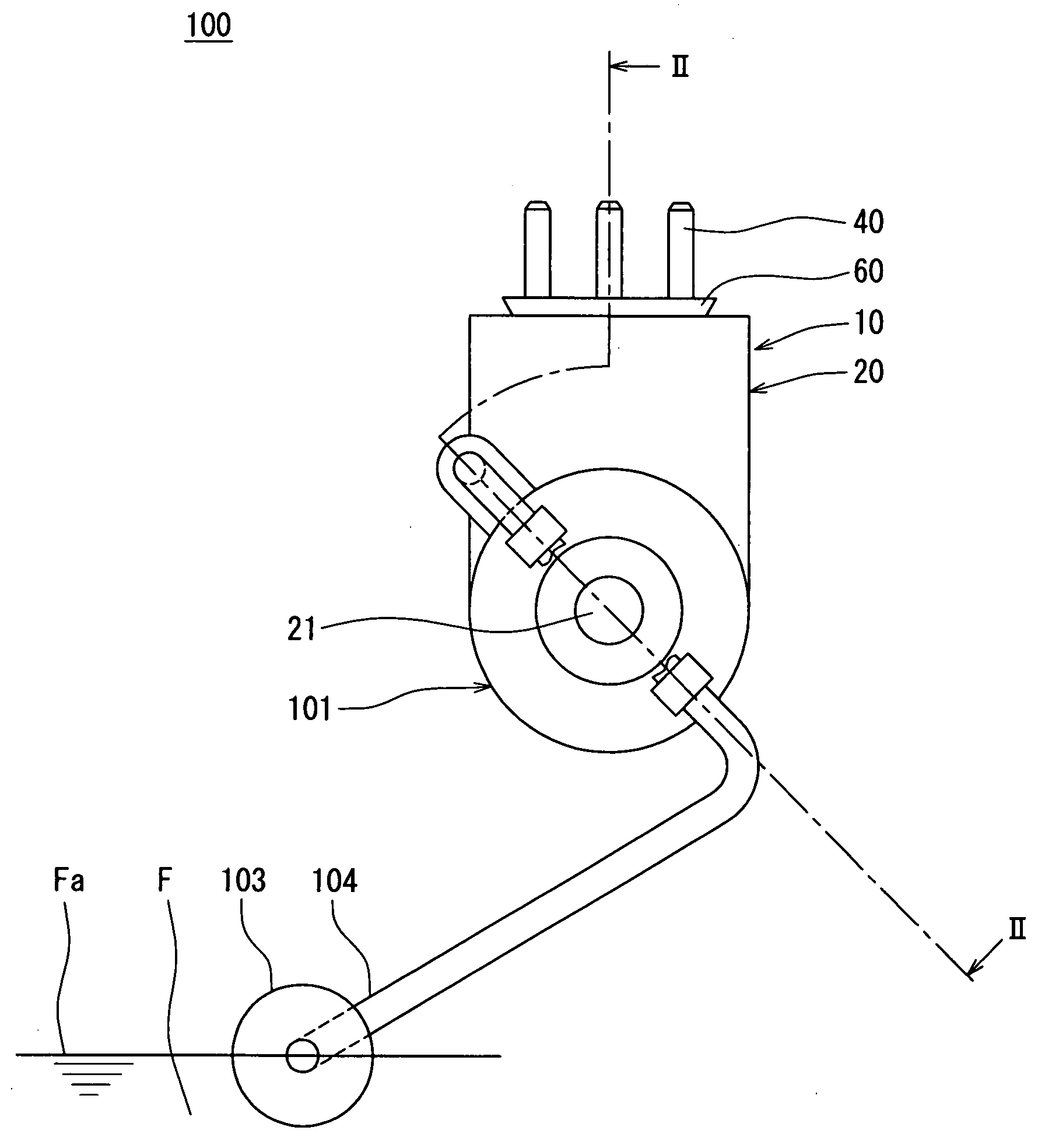
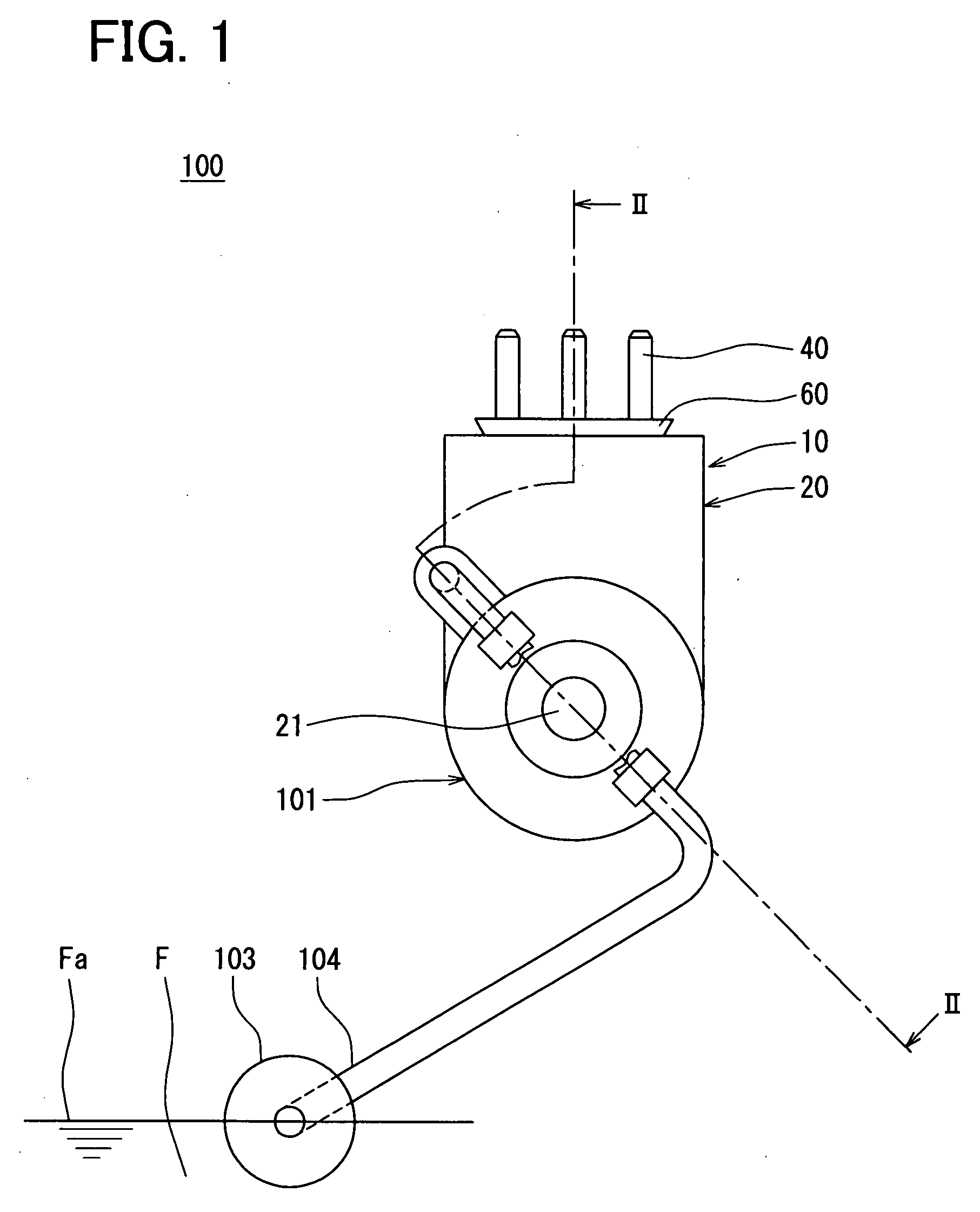
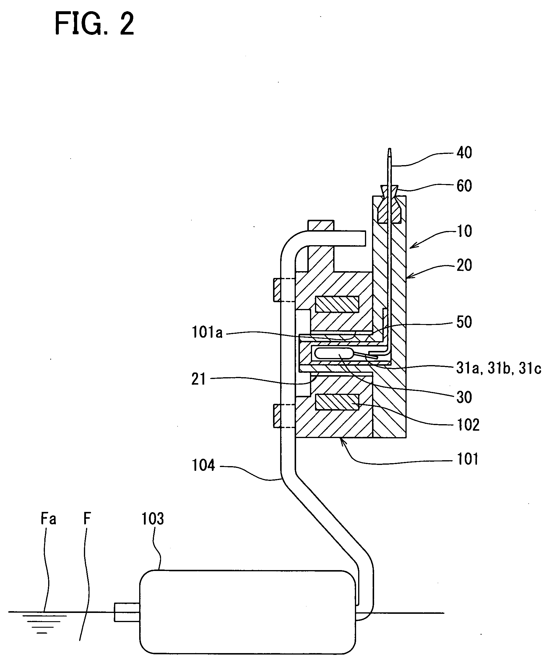
[0029]An electrical device according to an exampled embodiment of the present invention will be described with reference to FIGS. 1-5. For example, the electrical device can be suitably used as a body 10 of a fuel level gauge 100 which is arranged in a fuel tank of a vehicle to detect a liquid surface Fa of a fuel F in the fuel tank.

[0030]In FIG. 1 which shows the fuel level gauge 100 provided with the body 10 (electrical device), the state that the liquid surface Fa of the fuel F is at a substantially lowermost position is indicated. The upper side in FIGS. 1 and 2 corresponds to the upper side in the use state of the fuel level gauge 100.

[0031]As shown in FIGS. 1 and 2, the fuel level gauge 100 is provided with the float 103, the arm 104 and a holder 101 for holding a magnet 102. The float 103 is fixed at one end of the arm 104. The other end of the arm 104 is fixed to the holder 101. The holder 101 is rotatably held at the body 10. The float 103 constantly float...


PUM


Abstract

An electrical device includes a terminal connected with an electronic component, a pliant member which contacts a part of the terminal in a longitudinal direction of the terminal and covers a whole circumference of the part, and a casing for holding the electronic component and the terminal and the pliant member. The casing is molded by a resin material with the electronic component, the terminal and the pliant member being insert-molded. The end portion of the terminal of an opposite side to the electronic component extends to an outer side of the casing. One part of the pliant member is covered by the casing and the other part thereof is exposed to the outer side of the casing. The pliant member is compressed in a direction substantially orthogonal to the longitudinal direction of the terminal.

Description

[0001]In this case, the end of the terminal is exposed to the outer side of the resin material to be connectable with an exterior electrical circuit, so that the Hall element can be electrically connected with the exterior circuit. A rubber material is arranged at a halfway (of longitudinal direction thereof) of the terminal, in such a manner that the rubber material covers the whole circumference of the terminal. The rubber material is also inert-molded in the resin material along with the above-described molding.[0002]In this case, the fixing device of the liquid surface detecting device is arranged in a fuel tank and disposed at a position which is lower than the liquid surface position of a fuel in the fuel tank when the tank is filled up. Thus, the fixing member is completely dipped in the fuel in the case where the state of the fuel tank is between a full-tank state and a predetermined state (where liquid surface is at a predetermined position). Moreover, even when the liquid ...

Claims


Application Information

Patent Timeline
IPC IPC(8): G01B7/30
CPCG01F23/38H01H36/02H01F7/0289
Inventor YASUDA, ATSUSHIMIYAGAWA, ISAO
Owner DENSO CORP
Why Eureka
Try Eureka