Image process apparatus for three-dimensional model

Inactive Publication Date: 2007-12-20
FUJITSU LTD
View PDF23 Cites 11 Cited by
  • Summary
  • Abstract
  • Description
  • Claims
  • Application Information

AI Technical Summary

Benefits of technology

[0026]Therefore, the present invention enables a high speed generation of a 3D model of a gap space of the inside of a product and a three-di

Problems solved by technology

The above noted display method for a cross-sectional image of a 3D model has only been capable of visualizing a gap in two-dimension, thus making it difficult to comprehend a gap inside of a product correctly.
A vol

Method used


Image

  • Image process apparatus for three-dimensional model
  • Image process apparatus for three-dimensional model
  • Image process apparatus for three-dimensional model

Examples


embodiment

Preferred Embodiment

[0081]{Outline}

[0082]FIG. 2 is a diagram describing an outline of a preferred embodiment (“the present embodiment” hereinafter) of the present invention.

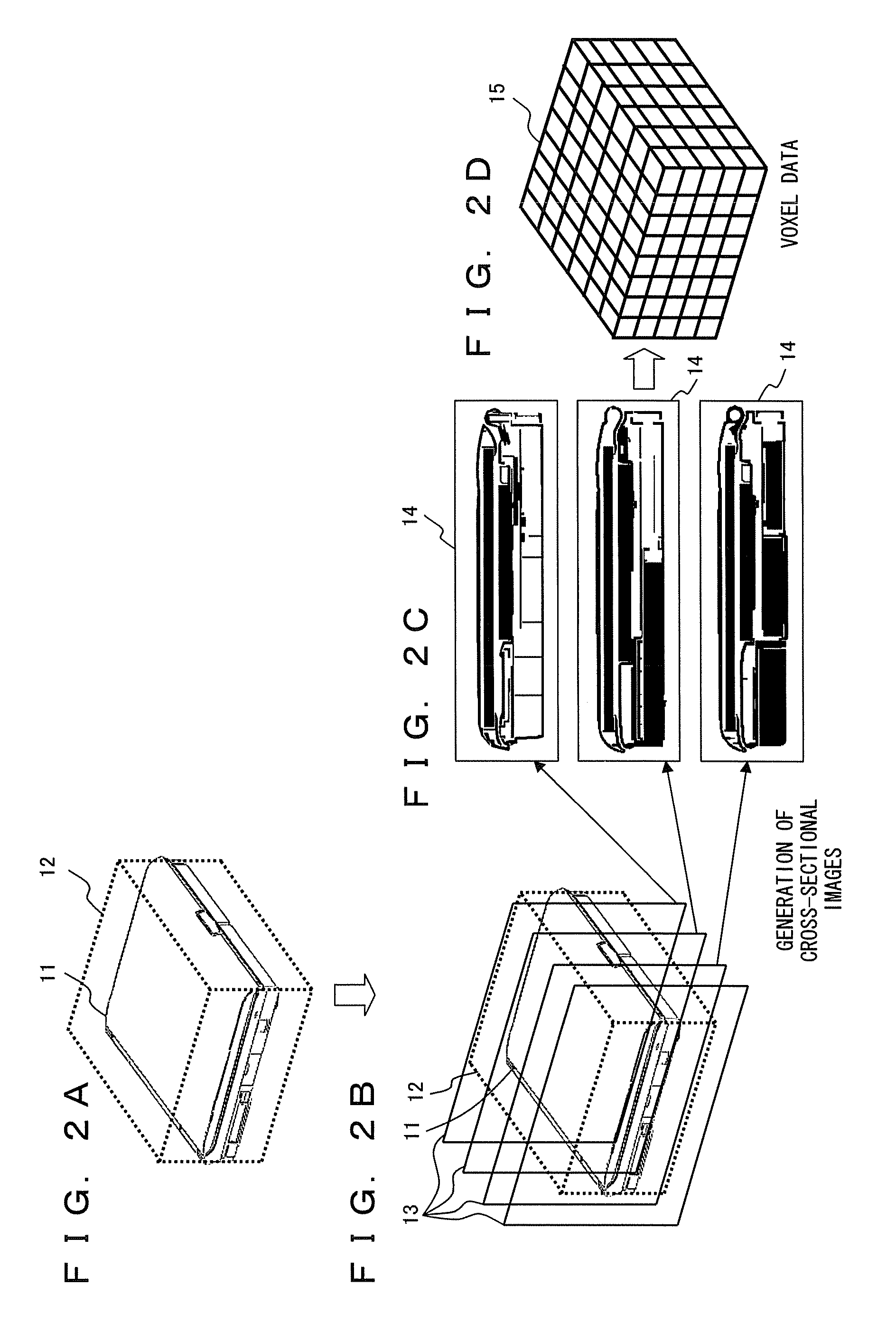
[0083]FIG. 2 gives a lap top PC as an example of a 3D product model.

[0084]As shown FIG. 2A, the present embodiment designates, for a 3D product model 11 as the target of a generation and volume calculation of a gap area, a calculation area 12 (a part indicated by the dotted lines) surrounding the entirety of the 3D product model 11. Then, it designates a plurality of cutting planes 13 for the calculation area 12 and cuts out the calculation area 12 by a plurality of cutting planes 13 as shown in FIG. 2B. Then, it generates an image on a crossing plane between the calculation area 12 and each cutting plane 13, which is obtained by the cutout, as a cross-sectional image 14 as shown in FIG. 2C. It then generates voxel data 15 by layering a plurality of cross-sectional images 14 as shown in FIG. 2D. The voxel data 15...


PUM


Abstract

A calculation area including a three-dimensional (3D) product model is specified, and a plurality of cross-sectional images is cut out from the calculation area. Each cross-sectional image is divided into plural pieces of voxel data, and voxel data of a gap area of the inside of a product is generated from the plural pieces of voxel data. A 3D model of the gap area of the inside of the product is generated, and also a volume of the gap area of the inside of the product is calculated, based on the voxel data of the gap area obtained by each cross-sectional image.

Description

BACKGROUND OF THE INVENTION[0001]1. Field of the Invention[0002]The present invention relates to an image process for a three-dimensional model, and in particular to an image process apparatus relating to a three-dimensional model of a gap space inside of a product.[0003]2. Description of the Related Art[0004]Ever increasing demand is a light weight and compact product for small electronic equipments including lap top personal computers (PC), personal digital assistants (PDA), portable phones, portable music players, et cetera. The product designs of these electronic equipments are carried out by computer aided designs (CAD). A high density mounting of component is a compulsory requirement for making a product compact, which accordingly requires a minimization of a gap in the inside of the product.[0005]A conventional technique for visualizing a gap inside of a product is a method for displaying a cross-sectional image of a three-dimensional (simply “3D” hereinafter) model. And a te...

Claims


Application Information

Patent Timeline
IPC IPC(8): G06T17/00
CPCG06T19/00G06T2200/04G06T2207/20141G06T2219/008G06T7/0081G06T17/00G06T7/11G06T7/187
Inventor HASHIMA, MASAYOSHISATO, YUICHIARITA, YUICHINOZAKI, NAOYUKI
Owner FUJITSU LTD
Why Eureka
Try Eureka