[0025]As a result of various investigations aimed at resolving the
night vision phenomenon alongside the
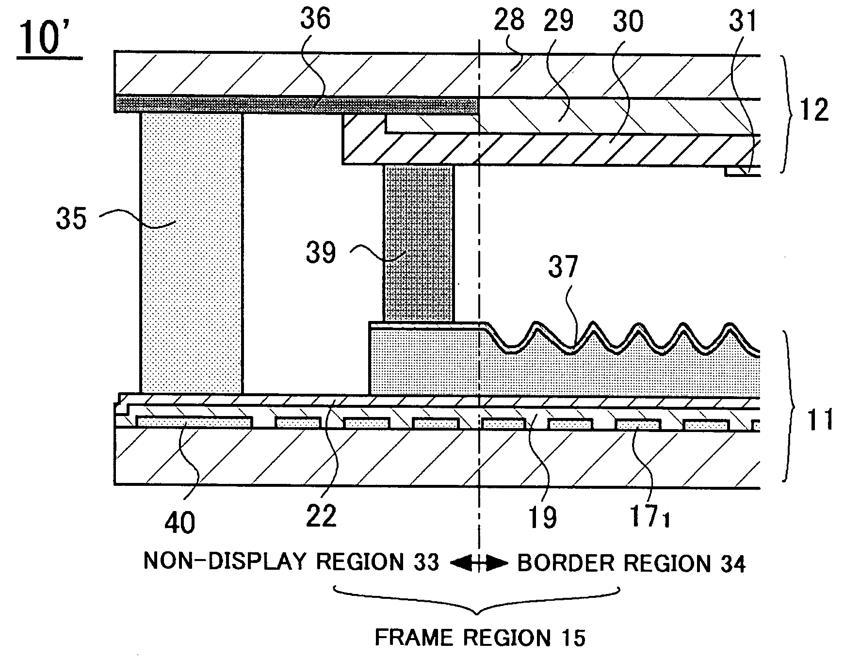
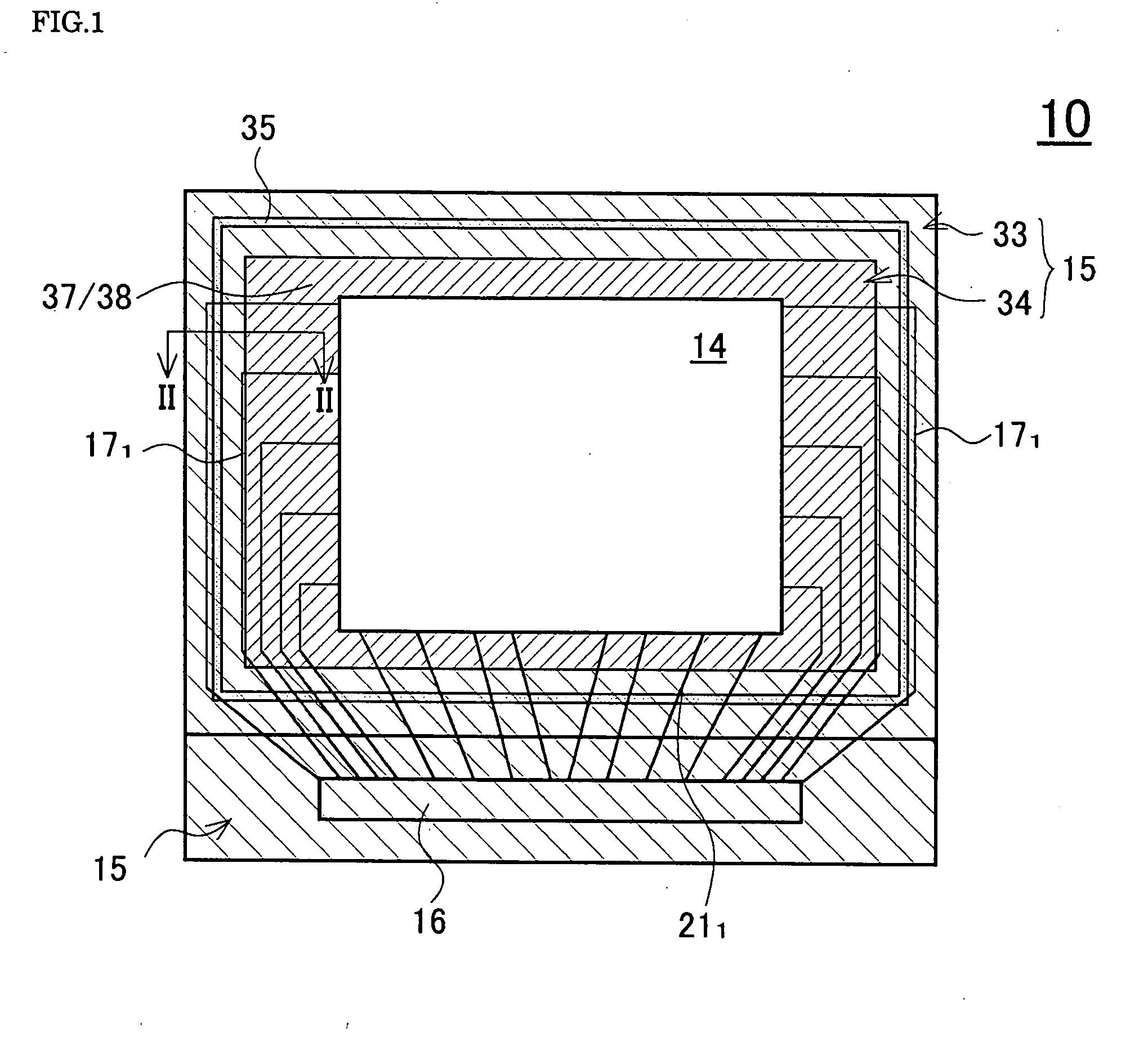
scan line wiring 171 of the border region 34 due to the foregoing causes, the inventors have found that the phenomenon of the border region 34 appearing dark along the scan line wiring 171 as described above is not generated, when there is no
potential difference between the opposed electrode 31 and the transparent electrode 38. However, it was difficult to adopt such a structure immediately, because of increase in manufacturing steps and manufacturing cost. By conducting further research, the inventors have found that when at least an outer peripheral side, or more preferably, all of the opposed electrode 31 at a position corresponding to the border region 34 does not exist, a state that the
electric field is not applied to the liquid crystal molecules can be created. This enables to eliminate the phenomenon that the border region 34 appears dark along the scan line wirings 171, thereby completing the present invention.
[0028]According to the above liquid
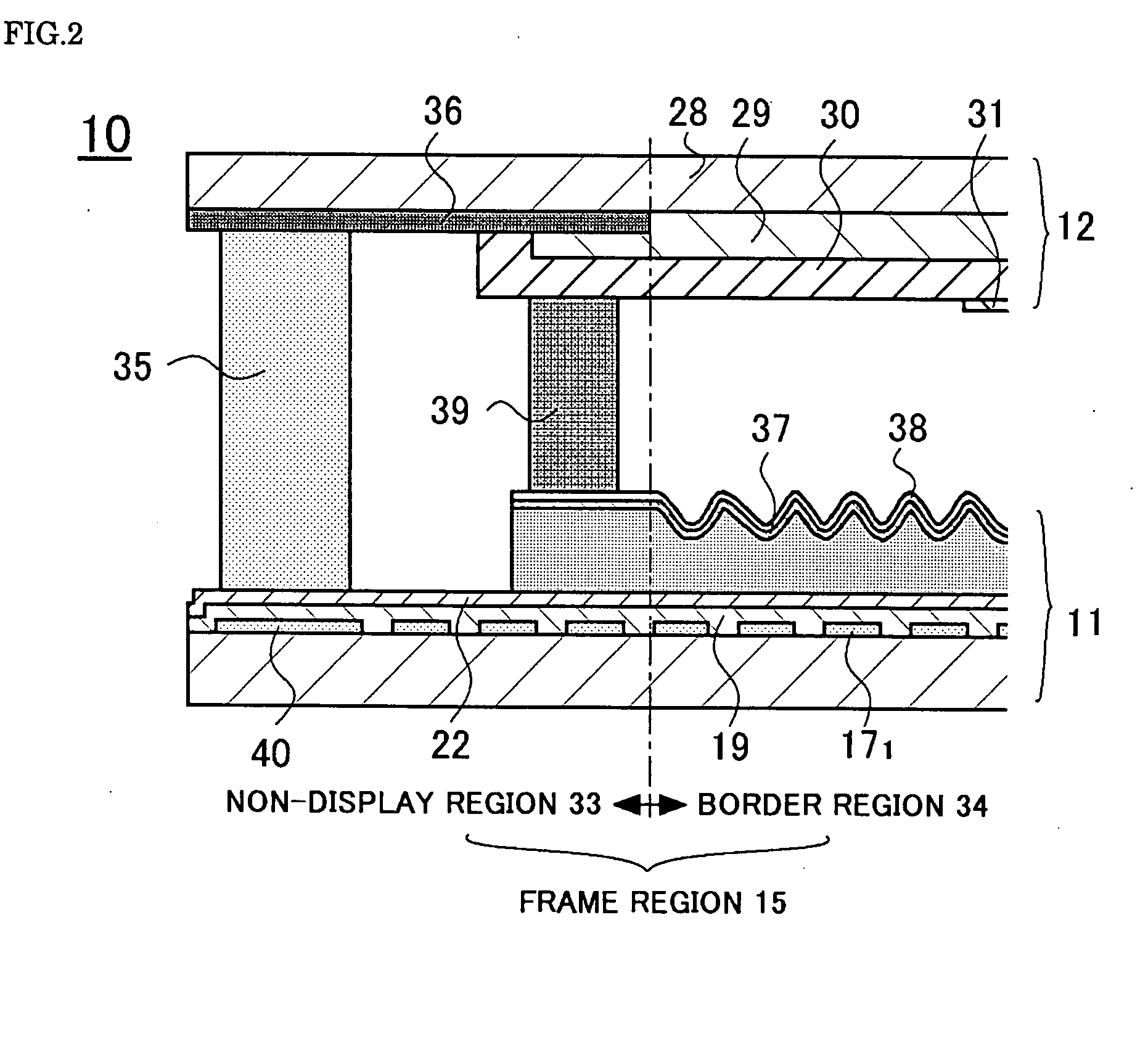
crystal display panel of the invention, at least a part of the outer peripheral side is not being provided to the common electrode at the position corresponding to the ornamental reflective part. As there is no
electric field applied to the liquid crystal layer by a
signal voltage being applied to the scan line wiring, it does not appear dark with lines along the scan line wiring as in the related art. As a result, the liquid
crystal display panel having the ornamental reflective part, that is, the border region, with an attractive appearance in white which uses reflection of external light by the reflector can be obtained. In such a case, by not providing all the common electrodes at the position corresponding to the ornamental reflective part, the
electric field applied to the liquid crystal layer by the
signal voltage being applied to the scan line wiring can be eliminated substantially and completely. But taking into account the likelihood of influence from electrostatic charges from outside, and to prevent the common electrode corresponding to the display region from misplacing by a
mask misalignment during manufacturing, it is preferable not to provide at least a part of the outer peripheral side of the common electrode at the position corresponding to the ornamental reflective part.
[0030]According to the above liquid crystal display panel, there is no need to adopt a special manufacturing method or a manufacturing step anew, so that the common electrode at the position corresponding to the ornamental reflective part does not provide a part of the outer peripheral side. As a result, the liquid crystal display panel having the border region which produces a good ornamental effect can be obtained with ease without increasing manufacturing steps.
[0032]According to the above liquid crystal display panel, the pixel electrode is formed in the display region. As the pixel electrode is formed by the transparent electrode, the structure of the ornamental reflective part can be made approximately the same as the structure of the display region, when the transparent electrode is also formed to the ornamental reflective part. As a result, a difference in appearance between the display region and the ornamental reflective part is reduced, and the liquid crystal display panel having the border region which produces a good ornamental effect can further be obtained.
[0034]According to the above liquid crystal display panel, light entered from outside becomes diffused reflected light, as the reflector of the ornamental reflective part has the concavoconvex structure. As a result, it looks pure white, and the liquid crystal display panel which produces a good ornamental effect can be obtained.
[0035]Also, in the above liquid crystal display panel, it is possible, not only for the transmissive type of liquid crystal display panel but also for the semi-transmissive or the reflective type, to obtain a liquid crystal display panel that yields an ornamental effect with a fine white appearance.

