

Cooling device and projector
- Summary
- Abstract
- Description
- Claims
- Application Information
AI Technical Summary
Benefits of technology
Problems solved by technology
Method used
Image

Examples
first exemplary embodiment
[0068]A first exemplary embodiment of the invention will be described below with reference to the drawings.
[0069]1 External Arrangement
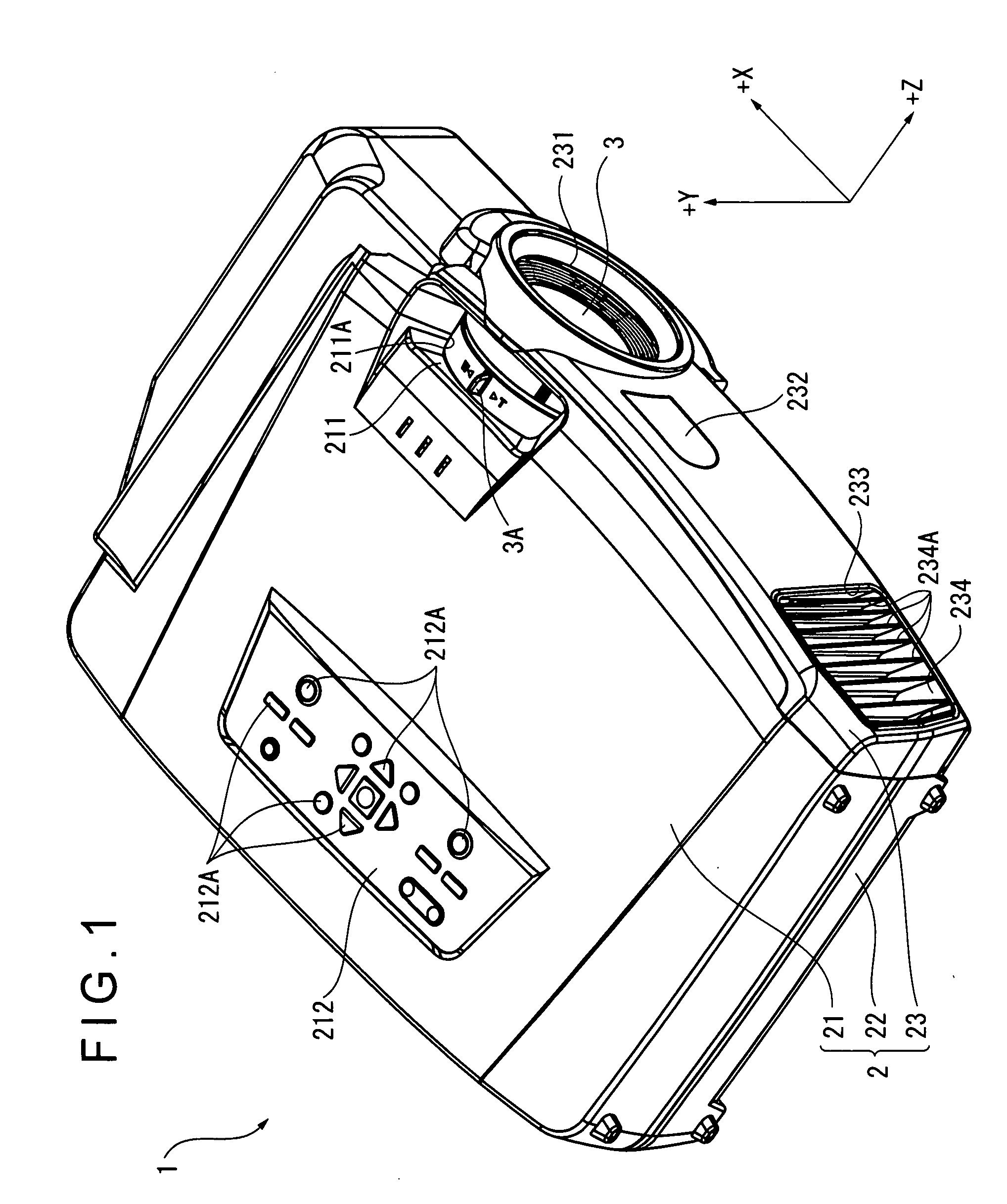
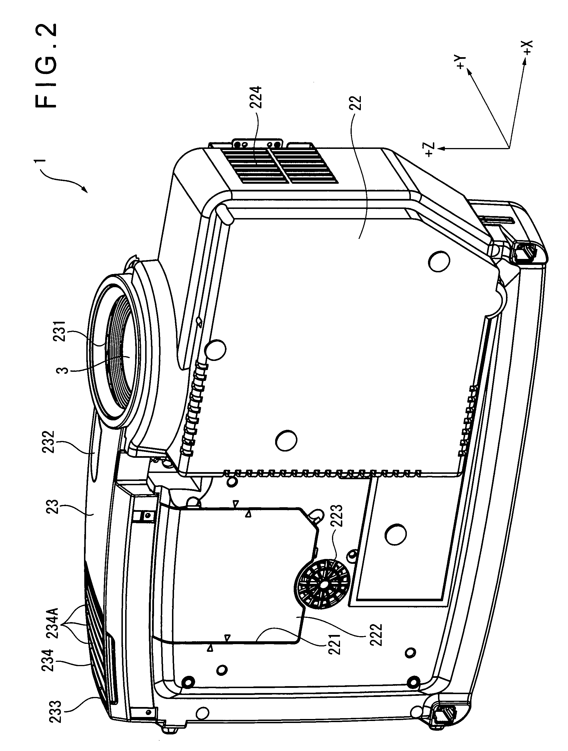
[0070]FIG. 1 is a perspective view showing an external appearance of a projector 1 of the first exemplary embodiment. Specifically, FIG. 1 is a perspective view of the projector 1 when seen from an upper front side. Note that, in FIG. 1, a direction in which an optical image is projected is defined as the Z axis and two axes orthogonal to the Z axis are defined as the X axis (a horizontal axis) and the Y axis (a vertical axis) for easy understanding. In the other figures, the same is applied.
[0071]The projector 1 modulates a light beam irradiated from a light source in accordance with image information to form an optical image and projects the optical image on a screen (not shown) in an enlarged manner. As shown in FIG. 1, the projector 1 includes a substantially rectangular parallelepiped exterior casing 2 and a projection lens 3 as a projection opt...
second exemplary embodiment
[0230]Next, a second exemplary embodiment of the invention will be described with reference to the attached drawings.
[0231]In the description below, the same components as those in the first exemplary embodiment are indicated by the same reference numerals for omitting or simplifying detailed description thereof.
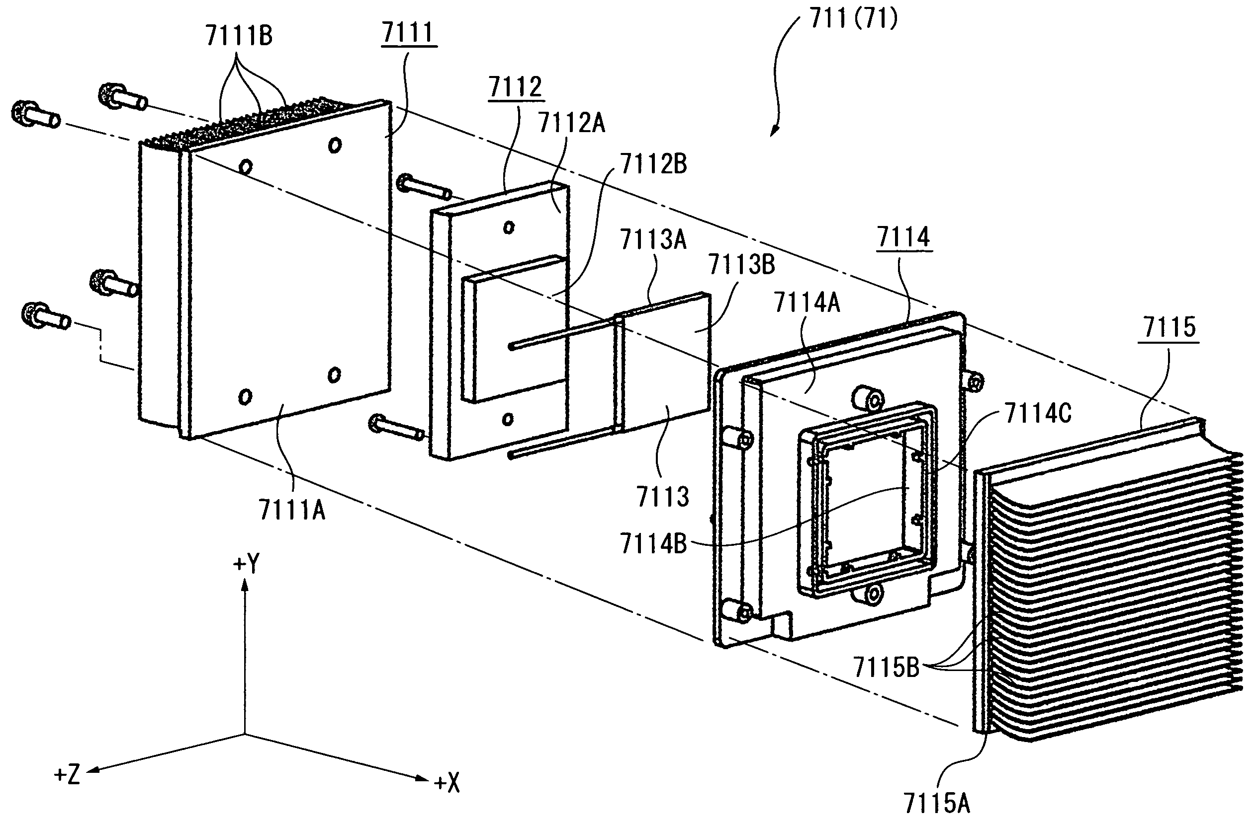
[0232]FIG. 22 shows a structure of a peltier unit 711A of the second exemplary embodiment. Specifically, FIG. 22 is a perspective view of the peltier unit 711A when seen from the plus X axis direction side (the side remote from the projection lens 3).
[0233]The second exemplary embodiment differs from the first exemplary embodiment in a shape of a heat-releasing-side heat conductive member 7116 of the peltier unit 711A as shown in FIG. 22. The other arrangements are the same as those of the first exemplary embodiment.
[0234]As shown in FIG. 22, similarly to the heat-releasing-side heat conductive member 7115, the heat-releasing-side heat conductive member 7116 includes the pla...
PUM
 Abstract
Description
Claims
Application Information