
Image Processing Apparatus and Method, and Image Processing Program

Active Publication Date: 2007-12-20
FUJIFILM CORP
View PDF2 Cites 37 Cited by
  • Summary
  • Abstract
  • Description
  • Claims
  • Application Information

AI Technical Summary

Benefits of technology

[0004] An object of the present invention is to so arrange it that an image correction can be applied appropriately even to an image containing a plurality subject types (photographic scenes).
[0024] In one embodiment, the image processing apparatus further includes subject-type designating means, the subject type-by-type certainty calculating means calculating the subject type-by-type certainty with regard to a subject type designated by the subject-type designating means or a subject type other than a subject type designated by the subject-type designating means. Further, the subject type-by-type correction value calculating means calculates the subject type-by-type correction value with regard to a subject type designated by the subject-type designating means or a subject type other than a subject type designated by the subject-type designating means. In a case where it is known beforehand that a specific subject type, for example, does not exist in an image represented by image data applied to the image processing apparatus, it is unnecessary to calculate degree of certainty and a correction value regarding the specific subject type. A specific type of subject type known beforehand to exist in the image (or specific subject type known beforehand not to exist in the image) is designated by the subject-type designating means. Degree of certainty and a correction value are calculated solely with regard to a designated subject type, or degree of certainty and a correction value are calculated solely with regard to a subject type other than a designated subject type. This makes it possible to shorten the processing time involved in the processing for calculating certainty and processing for calculating a correction value. Further, so arranging it that a degree of certainty and correction value regarding a specific subject type are forcibly not calculated prevents a situation in which degree of certainty and a correction value regarding the specific subject type are calculated in spite of the fact that the specific subject type does not exist in an image. This enhances correction accuracy.
[0029] With regard to an image of this kind, there is a possibility that the image processing apparatus will lower the degree of certainty of the subject type “human face” and raise the degree of certainty of the subject type “outside the scope of detection”. Upon taking note of these facts, the image processing apparatus calculates the degree of certainty regarding the lighting type and uses a correction quantity, which is calculated in accordance with a weight that is based upon the degree of certainty of the lighting type, in calculating a correction value regarding the subject type “outside the scope of detection”, thereby making it possible to improve the accuracy of image correction with regard to an image that contains a subject type that is outside the scope of detection.

Problems solved by technology

However, actual images also include those for which it is not possible to clearly distinguish to which preset photographic scene they belong.
In a case where an image has the characteristics of two scenes, there is the danger that the final result of a correction will be adversely affected when the image is judged to be either scene or the other.

Method used


Image

  • Image Processing Apparatus and Method, and Image Processing Program
  • Image Processing Apparatus and Method, and Image Processing Program
  • Image Processing Apparatus and Method, and Image Processing Program

Examples


first embodiment

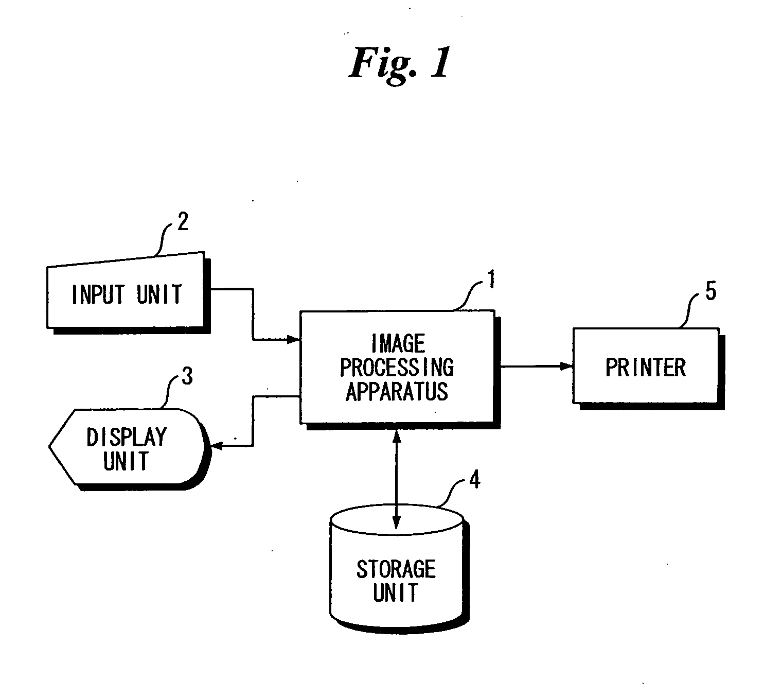
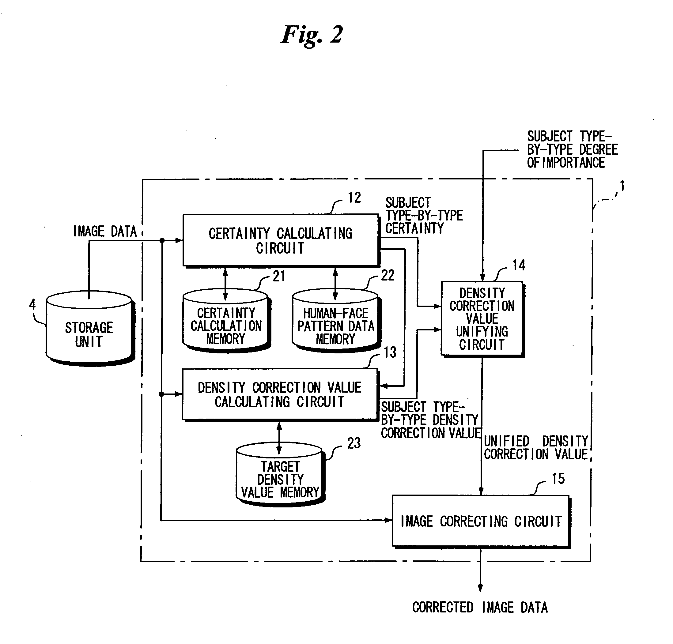
[0049]FIG. 1 is a block diagram illustrating the hardware configuration of an image processing system. FIG. 2 is a block diagram illustrating the electrical structure of an image processing apparatus 1, which constitutes the image processing system, together with a storage unit 4.

[0050] The image processing system comprises the image processing apparatus 1, an input unit 2 (keyboard, mouse, etc.) connected to the image processing apparatus 1, a display unit 3 (CRT display, liquid crystal display, etc.), the storage unit 4 (hard disk, etc.) and a printer 5.

[0051] Image data has been stored in the storage unit 4 connected to the image processing apparatus 1. Image data that has been read out of the storage unit 4 is input to the image processing apparatus 1 via an input interface (not shown). (Image data that is input to the image processing apparatus 1 shall be referred to as “input image data” below, and an image represented by input image data shall be referred to as an “input im...

second embodiment

[0168]FIG. 17 is a block diagram illustrating the electrical structure of an image processing apparatus 1A in a second embodiment. This apparatus differs from the image processing apparatus 1 of the first embodiment shown in FIG. 2 in that it is further provided with a certainty calculating circuit 16, a density correction quantity calculating circuit 17, a density correction value calculating circuit 18 for subject type “outside scope of detection”, and memories 24, 25. Further, as will be described later, processing in a density correction value calculating circuit 13A regarding subject type differs from that of the first embodiment.

[0169] In the image processing apparatus 1A of the second embodiment, a density correction value regarding the subject type “outside scope of detection” is not calculated in a density correction value calculating circuit 13A regarding subject type. The density correction value calculating circuit 13A of the second embodiment differs from the density c...


PUM


Abstract

A certainty calculating circuit calculates certainties representing to what degrees of confidence respective ones of images representing a predetermined plurality of types of subject are contained in an image represented by accepted image data, the calculation being performed for every prescribed type of subject based upon a feature value obtained from the accepted image data. A density correction value calculating circuit calculates density correction values with regard to respective ones of the plurality of subject types. Upon being weighted by respective ones of weights that are based upon the calculated certainties of each of the subject types, the plurality of density correction values are unified in a density correction value unifying circuit. The density of the image represented by the accepted image data is corrected in an image correcting circuit using the unified density correction value.

Description

TECHNICAL FIELD [0001] This invention relates to an image processing apparatus and method and to an image processing program. BACKGROUND ART [0002] A digital still camera having an image data processor 24 that includes a scene determination unit 31 is described in Japanese Patent Application Laid-Open No. 2002-218480. On the basis of a color histogram and whether an image contains an image representing a person, the scene determination unit 31 determines whether the image is in a photographic scene that is a snapshot, a portrait, a commemorative shot, scenery, a sunset, a night scene, a night-scene portrait, the sea, a scene shot under a fluorescent light source or scene shot under a tungsten light source. When the scene in which the image has been shot is determined, the image is subjected to correction processing, which has been set for every photographic scene, based upon the photographic scene determined. [0003] However, actual images also include those for which it is not possi...

Claims


Application Information

Patent Timeline
IPC IPC(8): G06K9/46
CPCG06K9/00228G06K9/00664G06T5/009H04N1/6027H04N1/4074G06V40/161G06V20/10G06T5/92
Inventor TAKEMOTO, FUMITO
Owner FUJIFILM CORP
Learn More