Vertical power unit and outboard engine system

a technology of vertical power unit and outboard engine, which is applied in marine propulsion, vessel construction, gearing, etc., can solve the problems of difficult to handle torque converters or output shafts, and achieve the effect of minimizing the bias of the center of gravity and being easy to handl

Active Publication Date: 2007-12-20
HONDA MOTOR CO LTD
View PDF7 Cites 5 Cited by
  • Summary
  • Abstract
  • Description
  • Claims
  • Application Information

AI Technical Summary

Benefits of technology

[0007] The present invention has been achieved in view of the above problem, and has an object to provide a vertical power unit which is easily handled by minimizing bias of the center of gravity due to the weight of a torque converter and a output shaft.

Problems solved by technology

In the vertical power unit or outboard engine system disclosed in U.S. Pat. No. 3,407,600, although a crankshaft of an engine is arranged so as to be largely apart from the central portion of the engine toward one side, an output shaft and a torque converter having relatively large weight are arranged immediately below and coaxially with the crankshaft, and thus the center of gravity of the vertical power unit or outboard engine system is biased further toward the crankshaft, whereby it is difficult to handle the torque converter or the output shaft.

Method used


Image

  • Vertical power unit and outboard engine system
  • Vertical power unit and outboard engine system
  • Vertical power unit and outboard engine system

Examples


Embodiment Construction

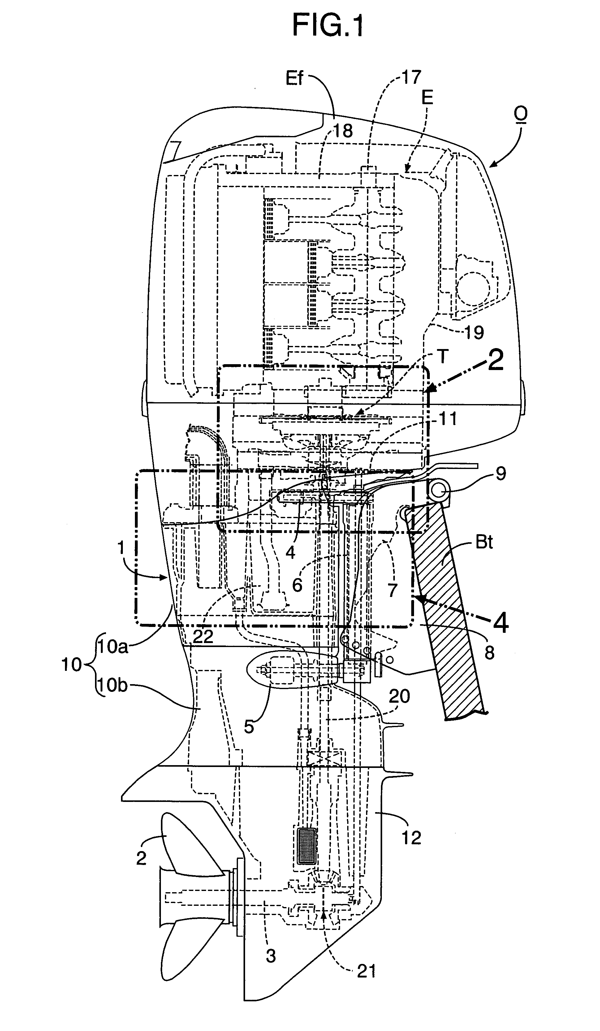
[0023] In FIG. 1, an outboard engine system O includes a casing 1 which has a water-cooled multi-cylinder four-stroke engine E mounted in its upper portion, and supports a propeller shaft 3 at its lower portion. The propeller shaft 3 has a propeller 2 provided at its rear end. A vertically-extending swivel shaft 6 is mounted to the casing 1 via an upper arm 4 and a lower arm 5 so as to situate in front of the casing 1. The swivel shaft 6 is rotatably supported by a swivel case 7 which is coupled to a stern bracket 8 via a horizontally-extending tilt shaft 9. The stern bracket 8 is cramped to a transom Bt of a body of a ship. Therefore, the casing 1 is horizontally rotatable around the swivel shaft 6, and vertically tiltable around the tilt shaft 9. The reference numeral Ef denotes a removable engine hood for covering the engine E.

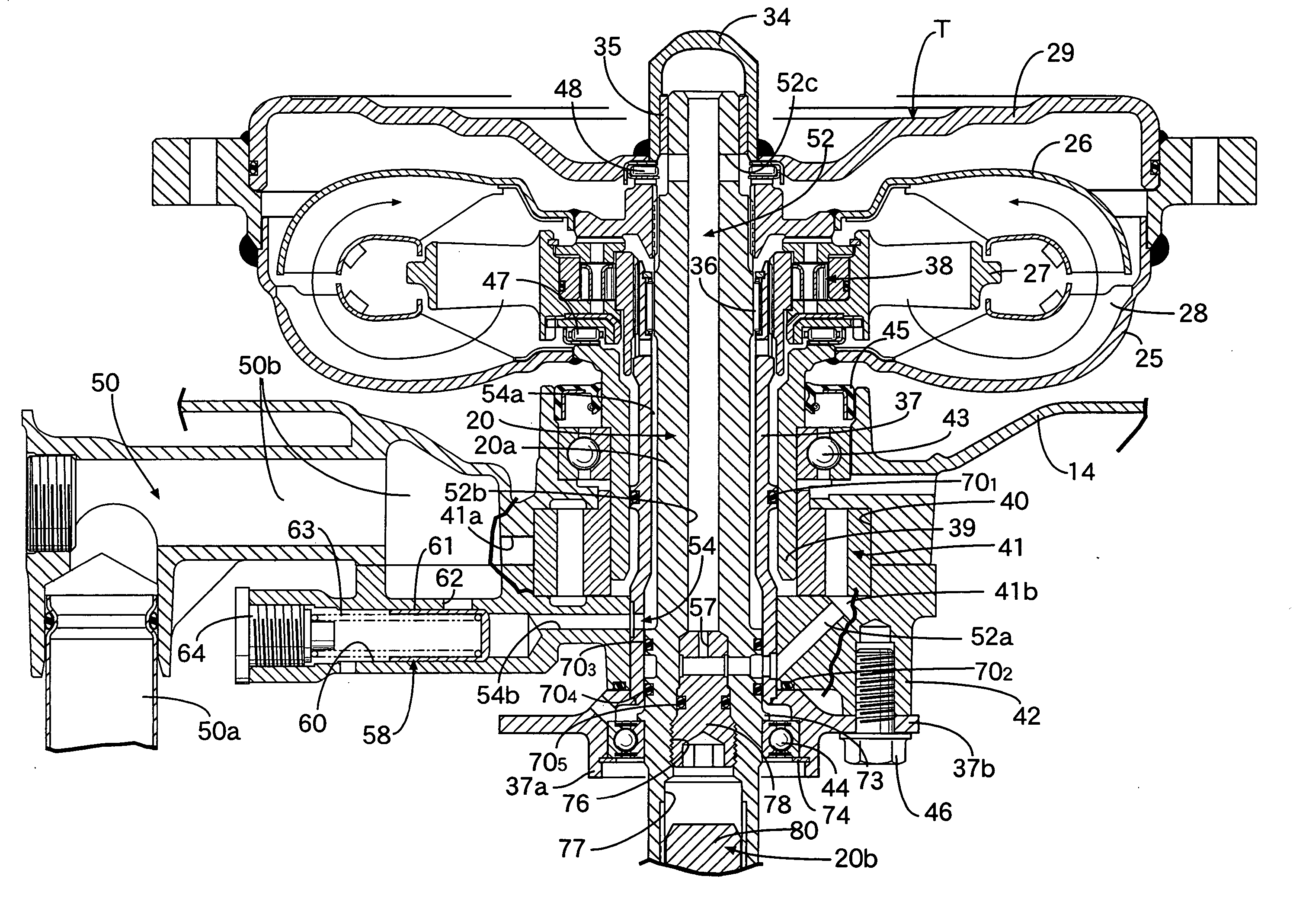
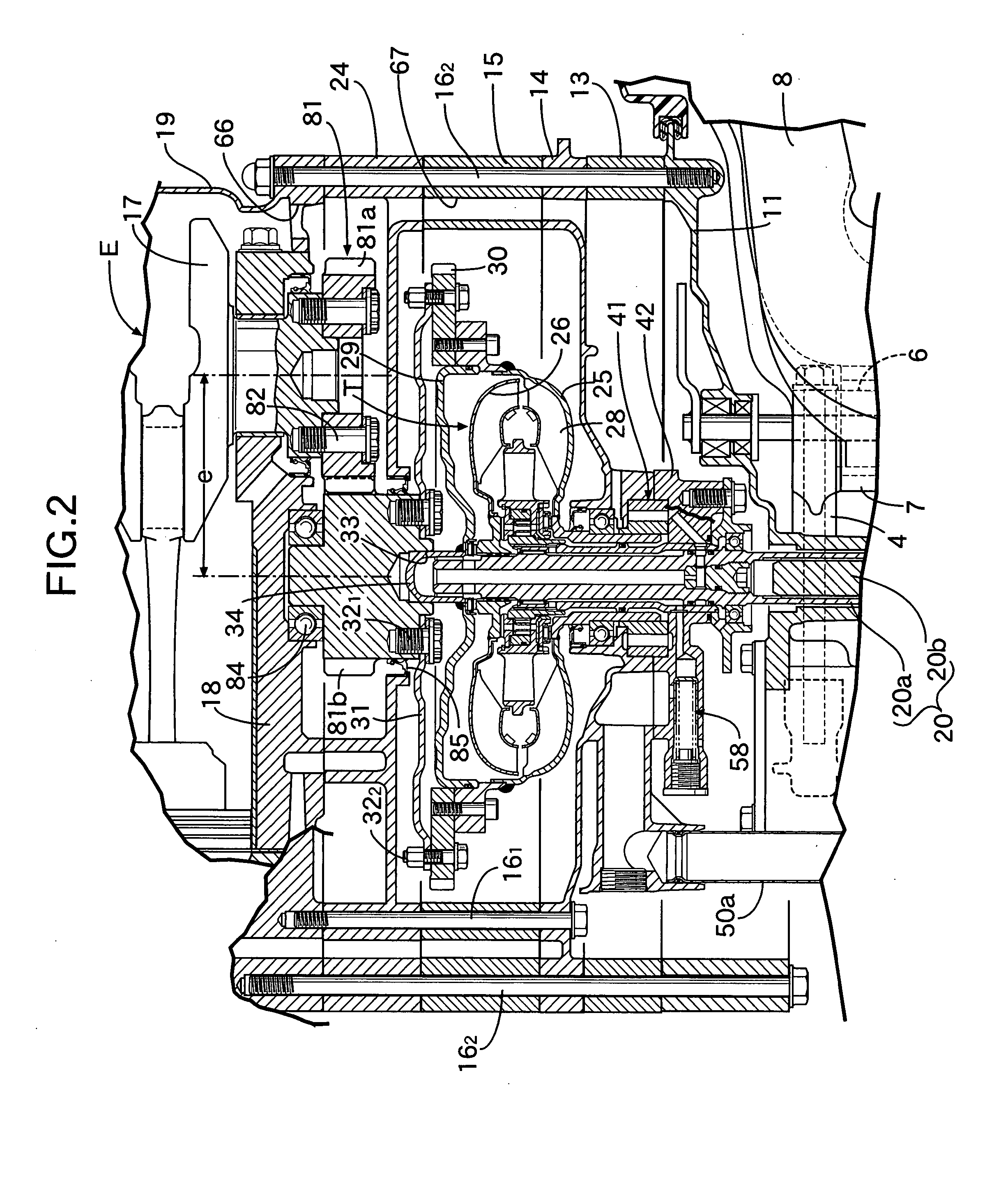
[0024] In FIG. 2, FIG. 3 and FIG. 4, the above casing 1 includes the extension case 10, the mount case 11 bolt-coupled to an upper end of the extension ca...


PUM

PropertyMeasurementUnit
weightaaaaaaaaaa
gravityaaaaaaaaaa
poweraaaaaaaaaa

Abstract

A vertical power unit includes: an engine having a vertically arranged crankshaft; a vertically arranged output shaft provided below the crankshaft; and a torque converter providing a connection between the crankshaft and the output shaft. The torque converter is arranged so as to be offset from the crankshaft toward a cylinder block of the engine. A transmission device is provided between the crankshaft and the torque converter. The output shaft is arranged coaxially with the torque converter. Thus, the center of gravity of the vertical power unit is positioned as close as possible to the central portion of the engine, thereby minimizing bias of the center of gravity due to the weight of the torque converter and the output shaft to facilitate the handling of the vertical power unit.

Description

RELATED APPLICATION DATA [0001] The present invention is based upon Japanese priority application No. 2006-145962, which is hereby incorporated in its entirety herein by reference. BACKGROUND OF THE INVENTION [0002] 1. Field of the Invention [0003] The present invention relates to an improvement of a vertical power unit comprising: an engine which has a vertically arranged crankshaft; a vertically arranged output shaft provided below the crankshaft; and a torque converter which is disposed between the crankshaft and the output shaft, and transmits power from the crankshaft to the output shaft. The present invention also relates to an improvement of an outboard engine system comprising: a casing coupled to a swivel case via a swivel shaft; an engine mounted in an upper part of the casing such that a crankshaft of the engine is vertically arranged and a cylinder block of the engine faces in a direction opposite to the swivel shaft; a torque converter; a vertically arranged output shaf...

Claims


Application Information

Patent Timeline
Patent Type & Authority Applications(United States)
IPC IPC(8): F16H41/00B63H20/00
CPCB63H20/002B63H20/14B63H20/20F16H41/30B63H2023/305F16H41/04B63H23/26
Inventor IDE, SHINICHIMATSUDA, YOSHIYUKI
Owner HONDA MOTOR CO LTD
Why Eureka
Try Eureka