
Porous sintered body, method of manufacturing porous sintered body, and method of manufacturing exhaust gas purifying apparatus

Active Publication Date: 2007-12-20
IBIDEN CO LTD
View PDF37 Cites 121 Cited by
  • Summary
  • Abstract
  • Description
  • Claims
  • Application Information

AI Technical Summary

Problems solved by technology

In recent years and continuing, there is a problem in which particulates contained in exhaust gas of internal combustion engines of various vehicles (e.g. buses, trucks) and machinery (e.g. construction machinery) adversely affect the environment and the human body.
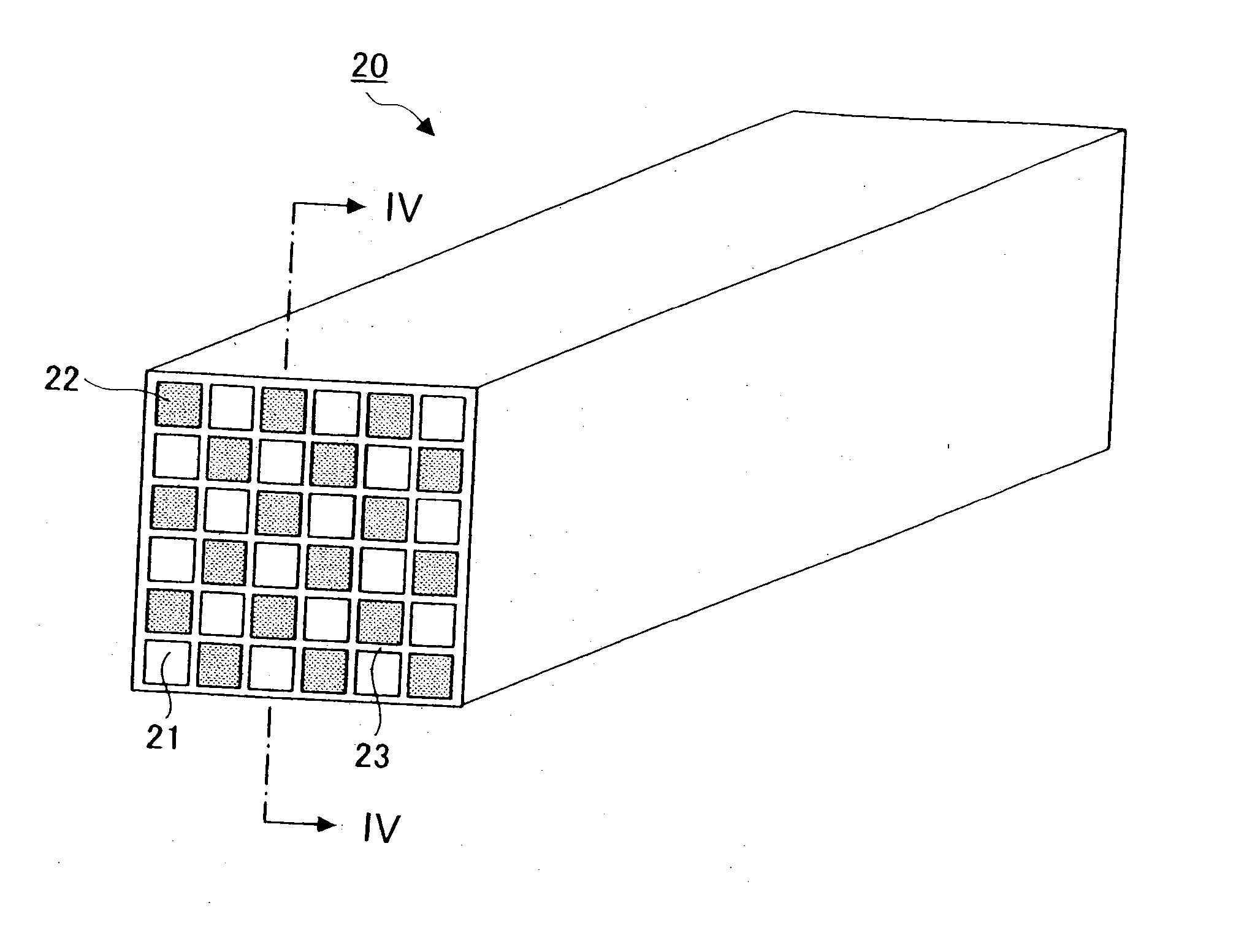
This is due to the fact that a low porosity increases the amount of damage caused by pressure when the exhaust gas flows through the honeycomb structural body.
This applies, particularly, to a honeycomb structural body carrying a large amount of catalyst since a part of the pores of the cell walls may become clogged when the catalyst is carried in the cell walls.
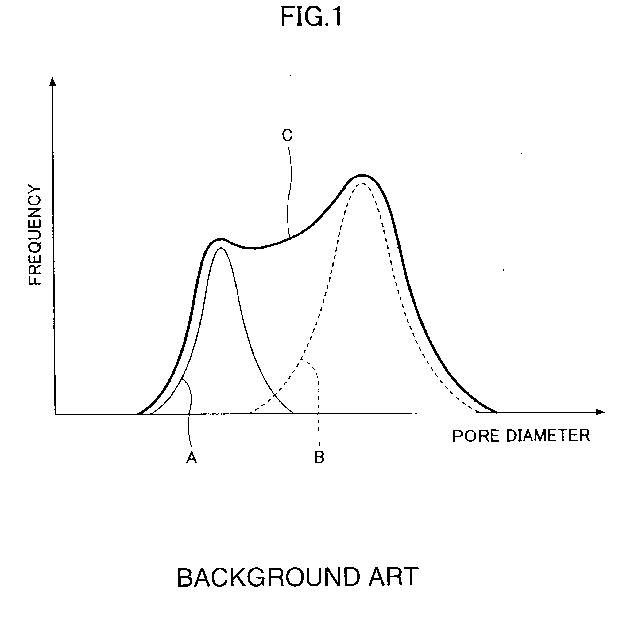
With a honeycomb structural body exhibiting a pore diameter distribution as C in FIG. 1, reduction of collection efficiency cannot be prevented even when the average pore diameter is controlled within a desired range.

Method used


Image

  • Porous sintered body, method of manufacturing porous sintered body, and method of manufacturing exhaust gas purifying apparatus
  • Porous sintered body, method of manufacturing porous sintered body, and method of manufacturing exhaust gas purifying apparatus
  • Porous sintered body, method of manufacturing porous sintered body, and method of manufacturing exhaust gas purifying apparatus

Examples


examples

[0095] The present invention is described in further detail with reference to the below-described examples of the present invention.

Fabrication of Honeycomb Structural Body of Example 1

[0096] First, a mixed compound is obtained by dry mixing coarse-grained silicon carbide particles having an average particle diameter of 20 μm (6000 parts by weight), fine-grained silicon carbide particles having an average particle diameter of 0.5 μm (2570 parts by weight), hollow acrylic particles (serving as the pore forming material) having an average particle diameter of 17.5 μm (300 parts by weight), and an organic binder of methyl cellulose (550 parts by weight).

[0097] Then, the mixed compound has added a plasticizer (“Unilube” manufactured by Nippon Oil & Fats Co. Ltd.) of 330 parts by weight, glycerin (used as a lubricant) of 150 parts by weight, and water of an adequate amount. After the mixed compound is further kneaded, the kneaded mixed compound is subjected to an extrusion process. As...


PUM

PropertyMeasurementUnit
Lengthaaaaaaaaaa
Lengthaaaaaaaaaa
Porosityaaaaaaaaaa

Abstract

A method of manufacturing a porous sintered body includes mixing at least two groups of silicon carbide particles and a pore forming material having an average particle diameter Y μm to obtain a molding material. The at least two groups of silicon carbide particles have different average particle diameters and have a first group of silicon carbide particles whose blending quantity by weight in the molding material is greatest among the at least two groups of silicon carbide particles. The first group have an average particle diameter X μm. The relationships 15≦X, 0.5·X≦Z≦0.9·X, and 0.8·Z≦Y≦1.8·Z are satisfied, wherein Z μm is an average pore diameter of the porous sintered body no less than 10 μm and no greater than 20 μm.

Description

CROSS-REFERENCE TO RELATED APPLICATIONS [0001] The present application claims priority under 35 U.S.C. §119 to Japanese Patent Application No. 2006-100410, filed Mar. 31, 2006, entitled “HONEYCOMB STRUCTURAL BODY AND METHOD OF MANUFACTURING THE SAME,” and Japanese Patent Application No. 2007-047945, filed Feb. 27, 2007, entitled “HONEYCOMB STRUCTURAL BODY AND METHOD OF MANUFACTURING THE SAME.” The contents of these applications are incorporated herein by reference in their entirety. BACKGROUND OF THE INVENTION [0002] 1. Field of the Invention [0003] The present invention relates to a porous sintered body, a method of manufacturing a porous sintered body, and a method of manufacturing an exhaust gas purifying apparatus. [0004] 2. Discussion of the Background [0005] In recent years and continuing, there is a problem in which particulates contained in exhaust gas of internal combustion engines of various vehicles (e.g. buses, trucks) and machinery (e.g. construction machinery) adversel...

Claims


Application Information

Patent Timeline
IPC IPC(8): B01J27/224B28B1/00C04B35/64
CPCB01D46/2418Y10T428/25B01D46/2459B01D2046/2437B01D2046/2496B01J23/002B01J23/63B01J23/83B01J35/04B01J35/10B01J37/0215B01J2523/00B32B2315/02C04B28/24C04B35/565C04B35/6263C04B35/80C04B35/806C04B37/005C04B38/0009C04B38/0019C04B2111/00198C04B2111/00793C04B2111/0081C04B2235/3418C04B2235/5224C04B2235/526C04B2235/5436C04B2235/5445C04B2235/5472C04B2235/656C04B2235/6567C04B2237/083C04B2237/365F01N3/0222F01N2330/06F01N2330/30F01N2330/48F01N2450/28B01D46/2429Y10T428/24149Y10T428/24727C04B38/0054C04B38/0074C04B38/0645C04B38/0655C04B38/08C04B14/32C04B14/4656C04B24/383B01J2523/31B01J2523/41B01J37/0018B01D46/2498B01J35/56B01J35/60B01D39/00B01D46/24491
Inventor OHNO, KAZUSHIGEKUNIEDA, MASAFUMIFUJITA, YUKI
Owner IBIDEN CO LTD
Learn More