
Method of Measuring Transverse Sensitivity of Sensor for Detecting Acceleration and Acceleration Measuring Method

a transverse sensitivity and sensor technology, applied in the direction of acceleration measurement in multiple dimensions, acceleration measurement using interia forces, instruments, etc., can solve problems such as clear mistakes, and achieve the effect of improving accuracy and simple structur

Inactive Publication Date: 2007-12-27
NAT INST OF ADVANCED IND SCI & TECH
View PDF2 Cites 36 Cited by
  • Summary
  • Abstract
  • Description
  • Claims
  • Application Information

AI Technical Summary

Benefits of technology

[0044] Advantages of the present invention are as follows:
[0045] (1) The matrix sensitivity of a sensor for detecting acceleration can be measured using a uniaxial vibration generator with a simple structure and a jig.
[0046] (2) Generally, the accuracy of the acceleration measurement can be improved. The reason for this will be described below.
[0047] Assume that a triaxial accelerometer is used for measuring the translational acceleration motion in a three-dimensional space. In this case, the matrix sensitivity is defined by the following expression. (Vox⁡(t)Voy⁡(t)Voz⁡(t))=(SxxSxySxzSyxSyySyzSzxSzySzz)⁢(aix⁡(t)aiy⁡(t)aiz⁡(t))(7)
[0048] For the sake of simplicity, assume that the diagonal components of the sensitivity matrix are all one, and

Problems solved by technology

A first problem is that the accelerometer / acceleration sensor is a device for measuring the acceleration as described in ISO 2041 Vibration and shock terminology, and that the acceleration is a vector quantity as taught by elementary physics or written in the standard.
However, this is a clear mistake.

Method used


Image

  • Method of Measuring Transverse Sensitivity of Sensor for Detecting Acceleration and Acceleration Measuring Method
  • Method of Measuring Transverse Sensitivity of Sensor for Detecting Acceleration and Acceleration Measuring Method
  • Method of Measuring Transverse Sensitivity of Sensor for Detecting Acceleration and Acceleration Measuring Method

Examples


Embodiment Construction

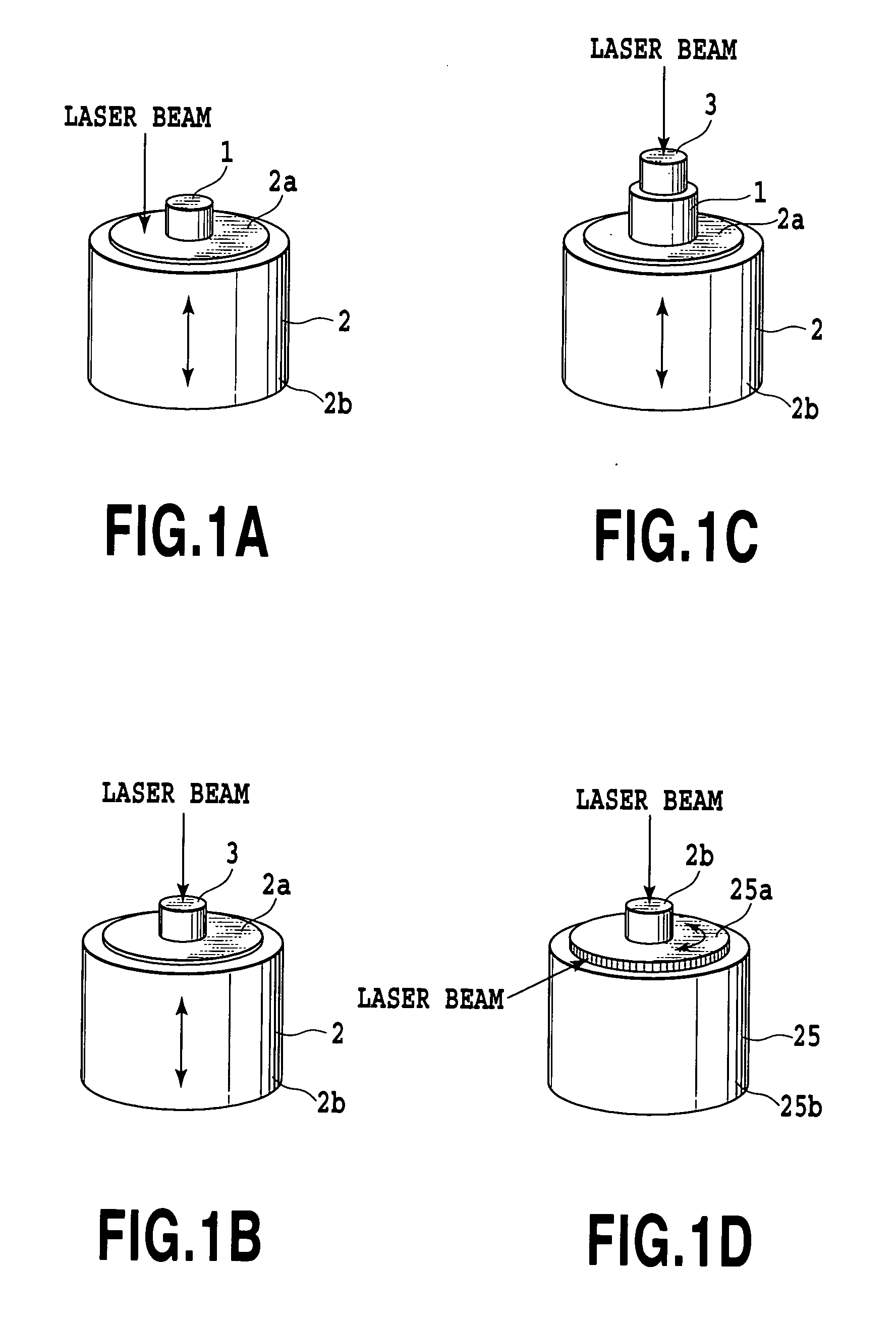
[0086] The following embodiments employ acceleration sensors as shown in FIG. 4A-FIG. 4D:

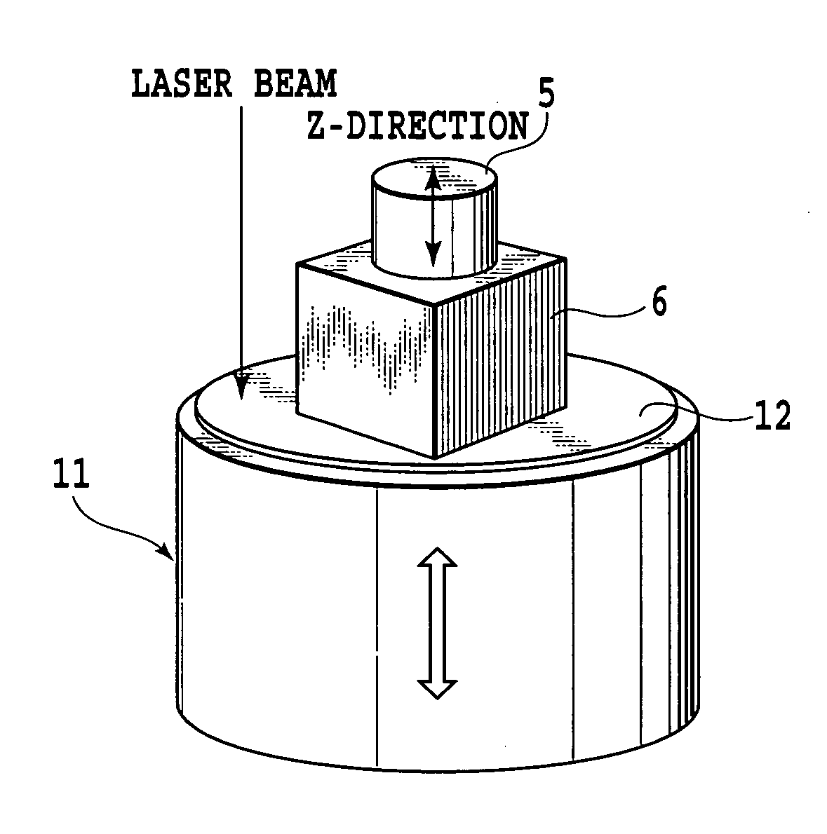
[0087]FIG. 4A shows a single uniaxial acceleration sensor 5 mounted on a surface of a cubical block 6 serving as a jig;

[0088]FIG. 4B shows two uniaxial acceleration sensors 5 mounted on two surfaces of the cubical block 6 serving as a jig, respectively;

[0089]FIG. 4C shows three uniaxial acceleration sensors 5 mounted on three surfaces of the cubical block 6 serving as a jig, respectively; and

[0090]FIG. 4D shows a semiconductor accelerometer (which includes one having gyroscopic functions or angular acceleration measuring functions), which is to be mounted on a surface of a cubical block serving as a jig.

[0091] The definition of each surface of the cubical block, to which each sensor is mounted, is as shown in FIG. 5 or FIG. 6 (designated by reference symbols), and is common to all the sensors.

[0092]FIG. 4E shows coordinate axes (X-axis, Y-axis and Z-axis perpendicular to each other) of the...


PUM


Abstract

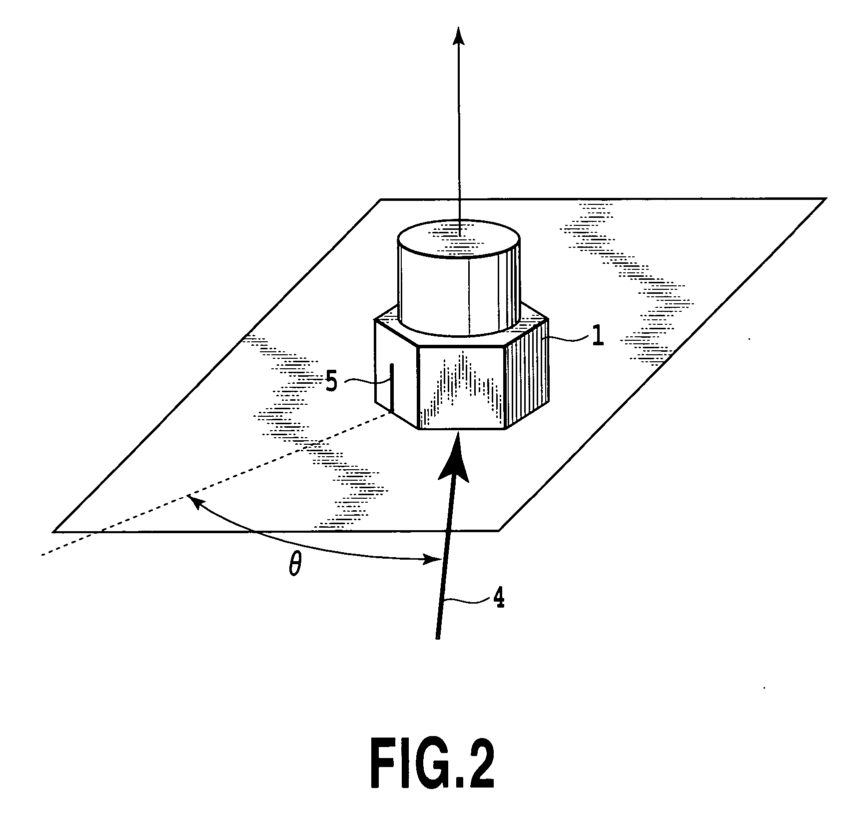
A sensor obtains transverse sensitivity in a sensitivity matrix of an acceleration sensor with a uniaxial vibration generator. The acceleration is measured by vibrating the table 12. As the measurement of the main axis sensitivity, transverse sensitivity Szx associated with the X-axis is obtained from measured results of the acceleration sensor 5 and measured results of a measuring instrument for measuring the surface motion of the table 12 independently. Likewise, transverse sensitivity Szy associated with the Y-axis is obtained by fixing on the table 12 the cubical block on which the acceleration sensor 5 is mounted in such a manner that the Y-axis direction defined with respect to the acceleration sensor 5 aligns with the vibration direction of the table 12.

Description

TECHNICAL FIELD [0001] The present invention relates to a method of measuring transverse sensitivity of a sensor for detecting acceleration and an acceleration measuring method. A technical field of the present invention relates to a field in which measurement of motion is essential such as measuring responses to vibrations involved in vehicle collision safety, car suspension control, robots, transportation equipment, equipment relating to atomic power generation, shipping, aerospace equipment, information equipment and human bodies, and measuring acceleration in ambient vibration. The term“acceleration” here means not only translational acceleration but also angular acceleration and angular velocity. As for multi-axial sensors, those that detect the translational acceleration and angular acceleration simultaneously are referred to as o-axial acceleration sensor, but those that detect the translational acceleration and angular velocity simultaneously are sometimes referred to as o-a...

Claims


Application Information

Patent Timeline
IPC IPC(8): G01P3/00G01P15/02G01P3/36G01P15/00G01P15/08G01P21/00
CPCG01P21/00G01P15/18
Inventor UMEDA, AKIRA
Owner NAT INST OF ADVANCED IND SCI & TECH
Learn More