Surface texture measuring instrument

a technology of surface texture and measuring instrument, which is applied in the direction of instruments, mechanical roughness/irregularity measurement, mechanical measuring arrangement, etc., can solve the problems of difficult to conduct constant force scanning control, and inability to maintain high precision, etc., and achieve the effect of small oscillation level

Active Publication Date: 2007-12-27
MITUTOYO CORP
View PDF2 Cites 8 Cited by
  • Summary
  • Abstract
  • Description
  • Claims
  • Application Information

AI Technical Summary

Benefits of technology

[0060]According to the aspect of the invention, when the contact portion contacts the workpiece surface and the oscillation of the stylus is suppressed, the oscillation level becomes small. From the difference in the oscillation, the measuring force that is applied on the conta

Problems solved by technology

However, it is sometimes difficult to conduct a constant force scanning control due to the surface profile, the surface texture and property fluctuation owing to material of the workpiece or disturbance input to the system.
When the constant force scanning control is difficult, namely when the force control is unstable, the scanning control may be oscillatory to cause variation in the measurement value, so that the high precision cannot be maintained.
For example, in a case shown in FIG. 18, when the scanning cont

Method used


Image

  • Surface texture measuring instrument
  • Surface texture measuring instrument
  • Surface texture measuring instrument

Examples


first embodiment

1)>

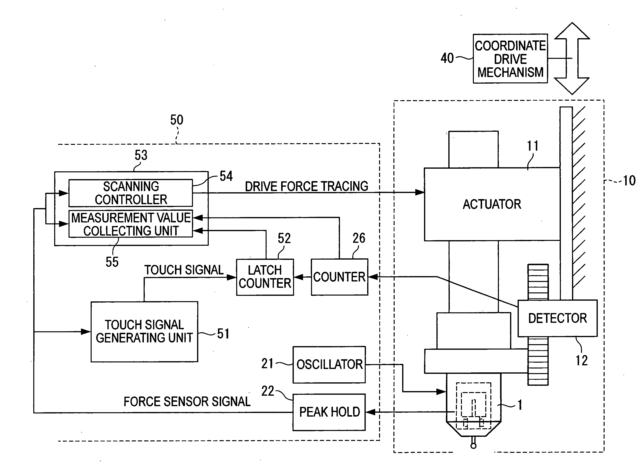
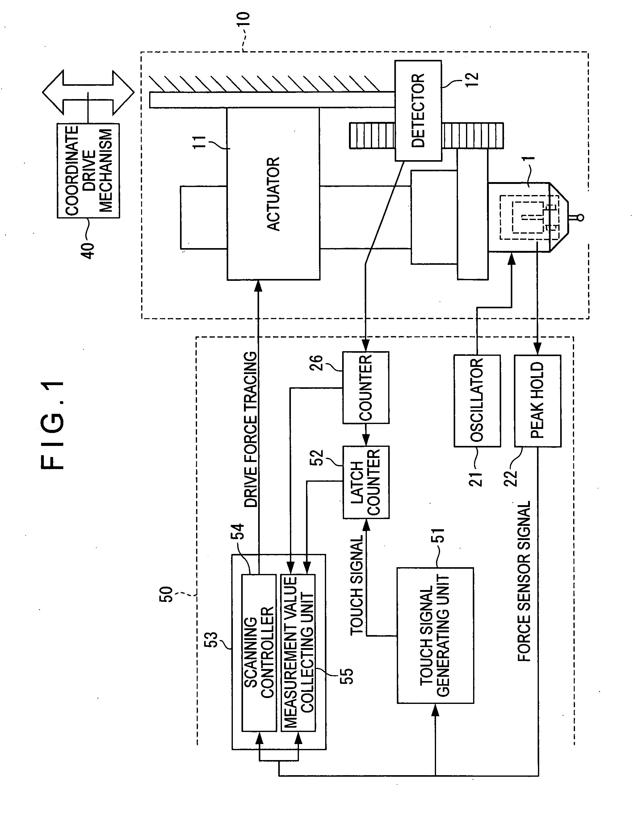
[0079]FIG. 1 is a block diagram showing a first embodiment of a surface texture measuring instrument according to the invention. The same components between FIG. 1 and FIG. 14 are given the same reference numerals and explanation for the components will be omitted or simplified in the description of FIG. 1.

[0080]The surface texture measuring instrument of the first embodiment includes a probe 10, a coordinate drive mechanism 40 and a controller 50 that controls the probe 10.

[0081]Similarly to FIG. 14, the probe 10 includes: a force sensor 1; an actuator 11 as a relative movement unit that moves (advances and retracts) the force sensor 1 relative to a workpiece W; and a detector 12 as a position detecting unit that detects a displacement amount in which the force sensor 1 is moved by the actuator 11 (namely, measuring point information on a measuring point of the workpiece W when measured by the force sensor 1), the detector 12 including a scale and a detecting head.

[0082]The coor...

second embodiment

4)>

[0107]In the first embodiment, the value of the latch counter 52 is collected at the timing of the generation of the touch signal on condition that the detection signal from the force sensor 1 exceeds the preset certain range. In the second embodiment, as shown in FIG. 4, a switch unit 56 that switches the scanning measurement mode and the touch measurement mode is provided.

[0108]The switch unit 56 includes a switching portion 56A that switches the scanning measurement mode and the touch measurement mode in accordance with the surface profile of the workpiece based on a selection by a user. In short, the switching portion 56A is inserted on a measurement value collecting unit 55 side to enable a switching between terminals of the counter 26 and the latch counter 52.

[0109]When the scanning controller 54 is in operation and the switching portion 56A of the switch unit 56 is switched to one side (a counter 26 side), the measurement value collecting unit 55 collects the position meas...

third embodiment

6)>

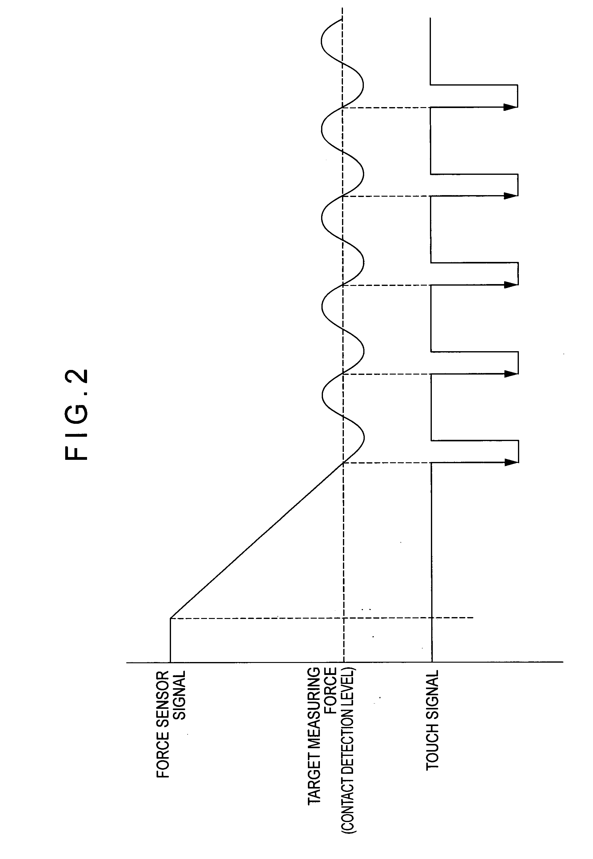
[0118]The first embodiment employs the arrangement in which a constant scanning force control is firstly conducted with an appropriately-set gain of the force control compensator 24 of the scanning controller 54. In the arrangement, the gain of the force control compensator 24 is adjusted or switched to high by the user when, for example, the scanning point of the force sensor 1 and the workpiece enters the region in which the detection signal from the force sensor 1 oscillates or it is adjusted or switched with the circuit provided for detecting that the detection signal from the force sensor 1 is oscillatory and that the oscillation range exceeds the preset certain range.

[0119]As shown in FIG. 6, the controller 50 in the third embodiment includes: a force control loop 28 that collects the force sensor signal (the detection measuring force) detected by the force sensor 1 as the measuring portion and drives the actuator 11 (the relative movement unit) such that the force sensor s...


PUM


Abstract

A surface texture measuring instrument includes a force sensor (1), an actuator (11) and a detector (12). The surface texture measuring instrument further includes: a scanning controller (54) that collects a detection signal from the force sensor (1) and drives the actuator such that the detecting signal coincides with a target measurement value; a touch signal generator (51) that generates a touch signal when the detection signal from the force sensor (1) coincides with the target measurement value; and a measurement value collecting unit (55) that collects a measurement value from a counter (26) at a predetermined time interval in a state where a fluctuation range of the detection signal from the force sensor (1) is within a preset range when a scanning controller is in operation, the latch counter (52) collecting a measurement value from a latch counter (52) each time the touch signal is generated in a state where the detection signal from the force sensor (1) oscillates and an amplitude exceeds the preset range.

Description

BACKGROUND OF THE INVENTION[0001]1. Field of the Invention[0002]The present invention relates to a surface texture measuring instrument. For example, the invention relates to a surface texture measuring instrument that measures a surface texture such as a profile or surface roughness of a workpiece by an oscillation-type force sensor.[0003]2. Description of Related Art[0004]As a surface texture measuring instrument that scans a surface of a workpiece and measures a surface texture such as a profile or surface roughness of the workpiece, a roughness measuring machine, a contour measuring machine, a roundness measuring machine, a coordinate measuring machine and the like are known.[0005]In the measuring machines, an oscillation-type force sensor is used as a sensor for detecting a workpiece surface based on fine displacement caused when a contact portion contacts the workpiece surface.<Oscillation-Type Force Sensor>[0006]As shown in FIG. 10, an oscillation-type force sensor 1 (a...

Claims


Application Information

Patent Timeline
IPC IPC(8): G01N3/08
CPCG01B3/008G01B7/28G01B7/012G01B7/008
Inventor IGASAKI, SHIROYAMAGATA, MASAOKI
Owner MITUTOYO CORP
Why Eureka
Try Eureka