Ergonomic machine control console

a machine control and ergonomic technology, applied in the field of control consoles, can solve the problems of operator fatigue, tooling can be relatively complicated and difficult to operate, and there is no way to rest the hand or arm

Inactive Publication Date: 2007-12-27
CATERPILLAR INC
View PDF43 Cites 45 Cited by
  • Summary
  • Abstract
  • Description
  • Claims
  • Application Information

AI Technical Summary

Benefits of technology

[0007]In one aspect, the present disclosure is directed to a control console associated with an armrest extending from a seat in a forward direction generally parallel with a seat plane of symmetry. The armrest has an upper surface intended to support an operator's forearm. The control console includes a base operatively connected to the armrest, and at least one operator interface device operatively connected to the base. The at least one operator interface device has a neutral axis inclined at an oblique angle relative to the upper surface of the armrest. The at least one operator interface device is pivotal in a fore / aft direction to initiate only a single function, the fore / aft direction being rotated outward away from the seat a predetermined angle relative to the forward direction of the armrest.
[0008]In another aspect, the present disclosure is directed to a method of controlling a machine. The method includes engaging a forearm with a first rest along the length of the forearm, and simultaneously adjusting a location of a second rest and at least one operator control device relative to the first rest. The method also includes positioning a palm on the second rest, and adjusting the location of the second rest relative to the first rest and the at least one operator control device. The method further includes actuating the at least one operator control device to control a function of machine.

Problems solved by technology

These tools can be relatively complicated and difficult to operate.
After a period of operating these control mechanisms, the operators became fatigued, with no way to rest the hand or arm while operating the various control mechanisms.
Further, because an operator's hand was required to travel from one actuating element to another, there may have been a delay between work tool manipulation that resulted in poor quality and / or low production.
Also, because these control mechanisms were fixed in a permanent location, they may have been inefficiently and / or non-ergonomically located for all machine operators.
Although the console of the '285 patent may have alleviated some of the problems associated with separate machine controls and operator fatigue, the console does not provide enough support or adjustability to the machine operator.
In addition, because the console is adjustable in only a single direction, it may still be inadequate for some operators.

Method used


Image

  • Ergonomic machine control console
  • Ergonomic machine control console
  • Ergonomic machine control console

Examples


Embodiment Construction

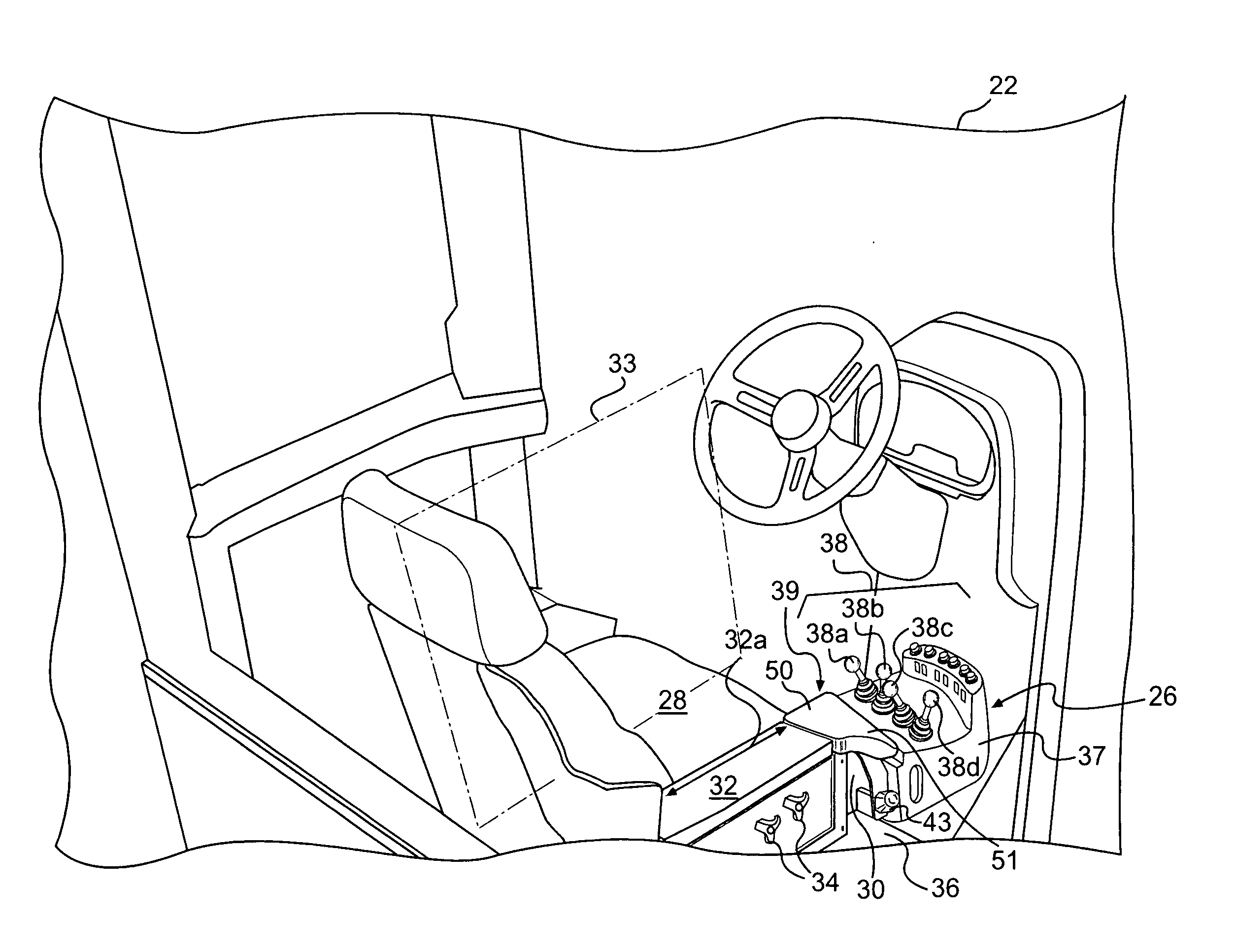
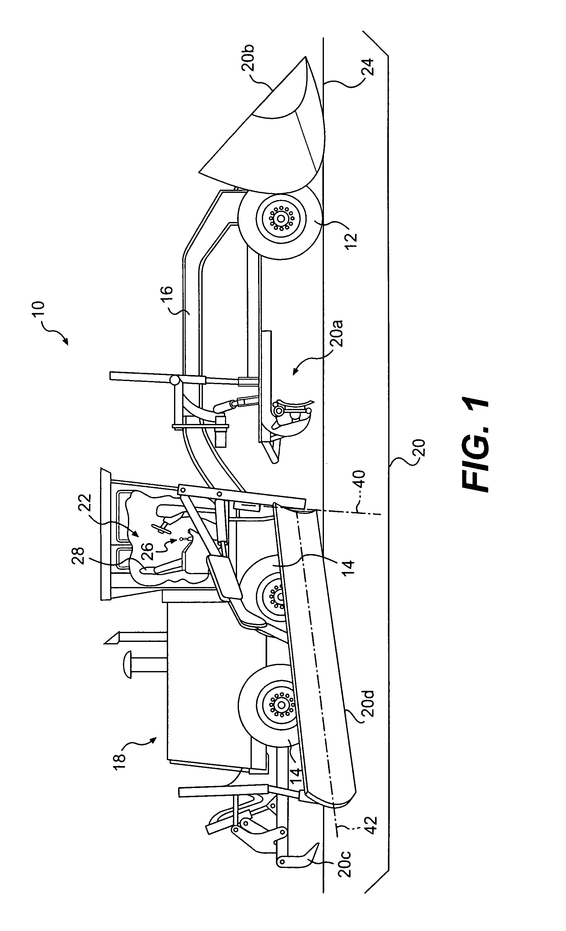
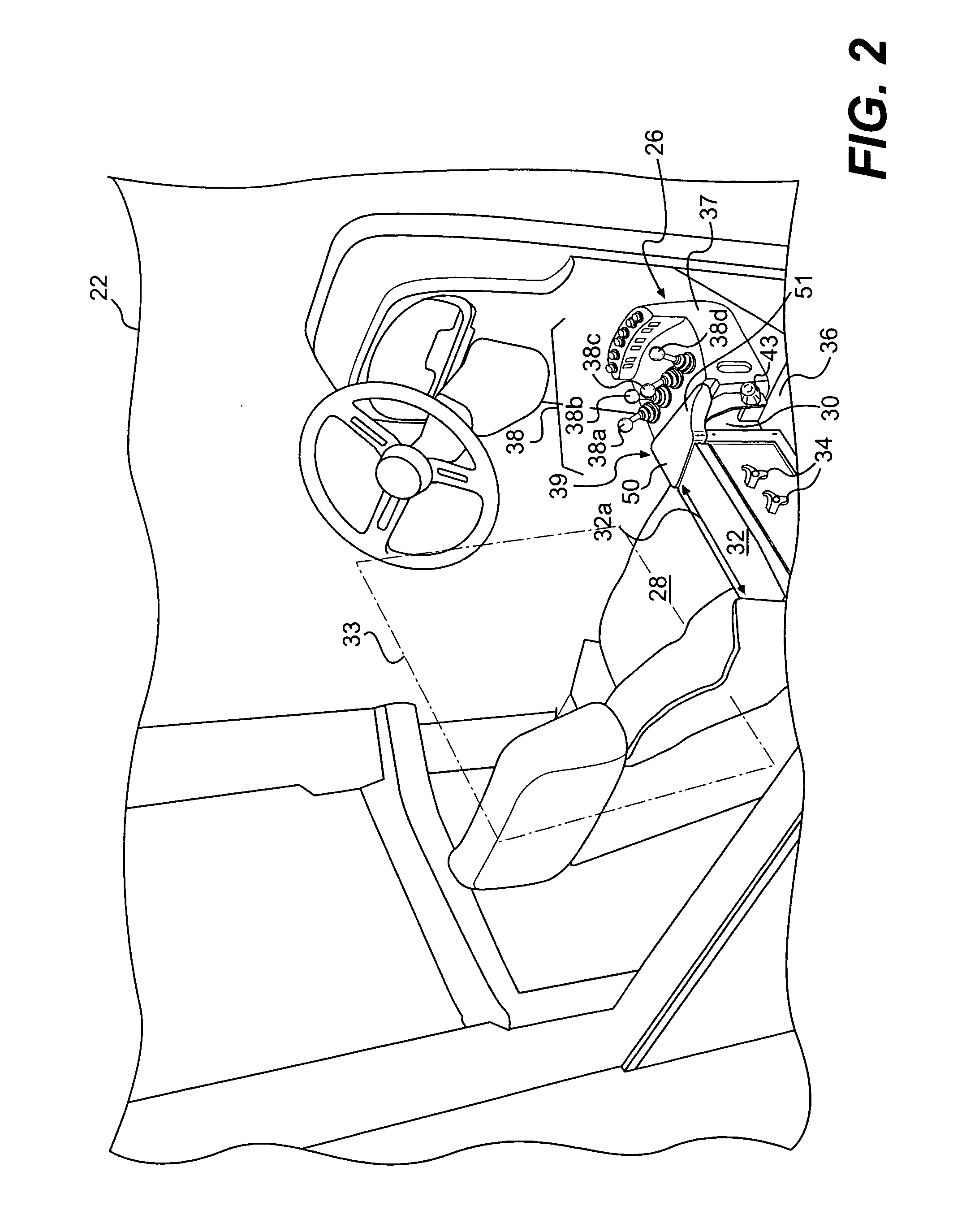
[0014]An exemplary embodiment of a machine 10 is illustrated in FIG. 1. Machine 10 may embody a fixed or mobile machine that performs some type of operation associated with an industry such as mining, construction, farming, transportation, or any other industry known in the art. For example, machine 10 may be an earth moving machine such as a wheel loader, an excavator, a motor grader, or any other earth moving machine. Machine 10 may include a steerable traction device 12, a driven traction device 14, and a frame 16 connecting steerable traction device 12 to driven traction device 14. Machine 10 may also include one or more work tools 20 and an operator station 22.

[0015]Both steerable and driven traction devices 12, 14 may include one or more wheels located on each side of machine 10 (only one side shown). Alternatively, steerable and / or driven traction devices 12, 14 may include tracks, belts, or other traction devices known in the art. Steerable traction devices 12 may or may not...


PUM


Abstract

A control console for a machine having a seat with a plane of symmetry is disclosed. The machine also has an armrest extending from the seat in a forward direction generally parallel with the plane of symmetry. The armrest has an upper surface intended to support an operator's forearm. The control console includes a base operatively connected to the armrest, and at least one operator interface device operatively connected to the base. The at least one operator interface device has a neutral axis inclined at an oblique angle relative to the upper surface of the armrest. The at least one operator interface device is pivotal in a fore/aft direction to initiate only a single function of the machine, the fore/aft direction being rotated outward away from the seat a predetermined angle relative to the forward direction of the armrest.

Description

TECHNICAL FIELD[0001]The present disclosure is directed to a control console and, more particularly, to an ergonomic machine control console designed to relieve operator fatigue.BACKGROUND[0002]Machines such as, for example, wheel loaders, motor graders, agricultural tractors, and other types of heavy equipment have a variety of tools attached to and controlled by the machine's operator. These tools can be relatively complicated and difficult to operate. Each tool may have a different operator interface with numerous controls for position, orientation, and other associated features and functions.[0003]Historically, machines have incorporated large, permanently located levers with complex mechanical linkages, multiple operating joints, and cables to provide the desired work tool functionality. Machines with such multiple control mechanisms required operators with high skill levels. After a period of operating these control mechanisms, the operators became fatigued, with no way to res...

Claims


Application Information

Patent Timeline
Patent Type & Authority Applications(United States)
IPC IPC(8): B60K26/00
CPCY10T74/20396B60K26/02
Inventor PROUD, MARC D.PRYOR, PATRICK ANDREWSILVERS, TIMOTHY J.
Owner CATERPILLAR INC
Why Eureka
Try Eureka