Electrical machine with improved windings

a technology of windings and electric motors, applied in windings, magnetic circuit rotating parts, magnetic circuit shapes/forms/construction, etc., can solve the problems of increased induced voltage and eddy current in windings, excessive losses and heating, and insufficient flux in generators

Inactive Publication Date: 2007-12-27
GENERAL ELECTRIC CO
View PDF25 Cites 6 Cited by
  • Summary
  • Abstract
  • Description
  • Claims
  • Application Information

AI Technical Summary

Problems solved by technology

However, the magnetic flux from the rotor and from the windings themselves may cause additional induced voltage and eddy currents in the windings.
The flux in a generator is not uniform.
Accordingly, the induced voltage varies from strand to strand, thereby causing excessive losses and heating.
This in turn sacrifices space in the slot.
However, transposition of strands in a wind

Method used


Image

  • Electrical machine with improved windings
  • Electrical machine with improved windings
  • Electrical machine with improved windings

Examples


Embodiment Construction

[0017]The following detailed description includes references to the accompanying drawings, which form a part of the detailed description. The drawings show, by way of illustration, specific embodiments in which the invention may be practiced. These embodiments, which are also referred to herein as “examples,” are described in enough detail to enable those skilled in the art to practice the invention. The embodiments may be combined, other embodiments may be utilized, or structural, logical and electrical changes may be made without departing from the scope of the present invention. The following detailed description is, therefore, not to be taken in a limiting sense, and the scope of the present invention is defined by the appended claims and their equivalents.

[0018]In this document, the terms “a” or “an” are used, as is common in patent documents, to include one or more than one. In this document, the term “or” is used to refer to a nonexclusive or, unless otherwise indicated. Furt...


PUM


Abstract

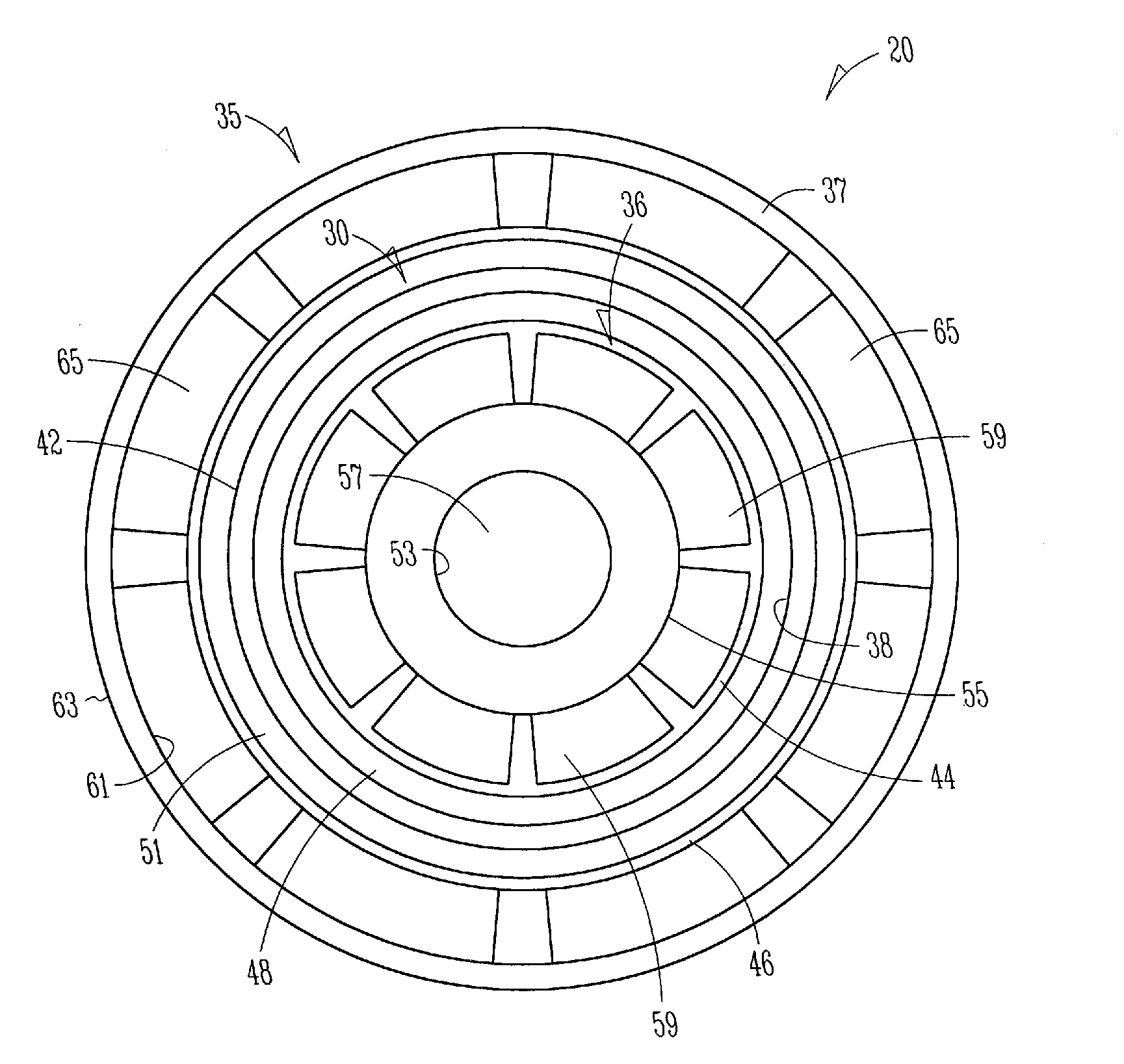
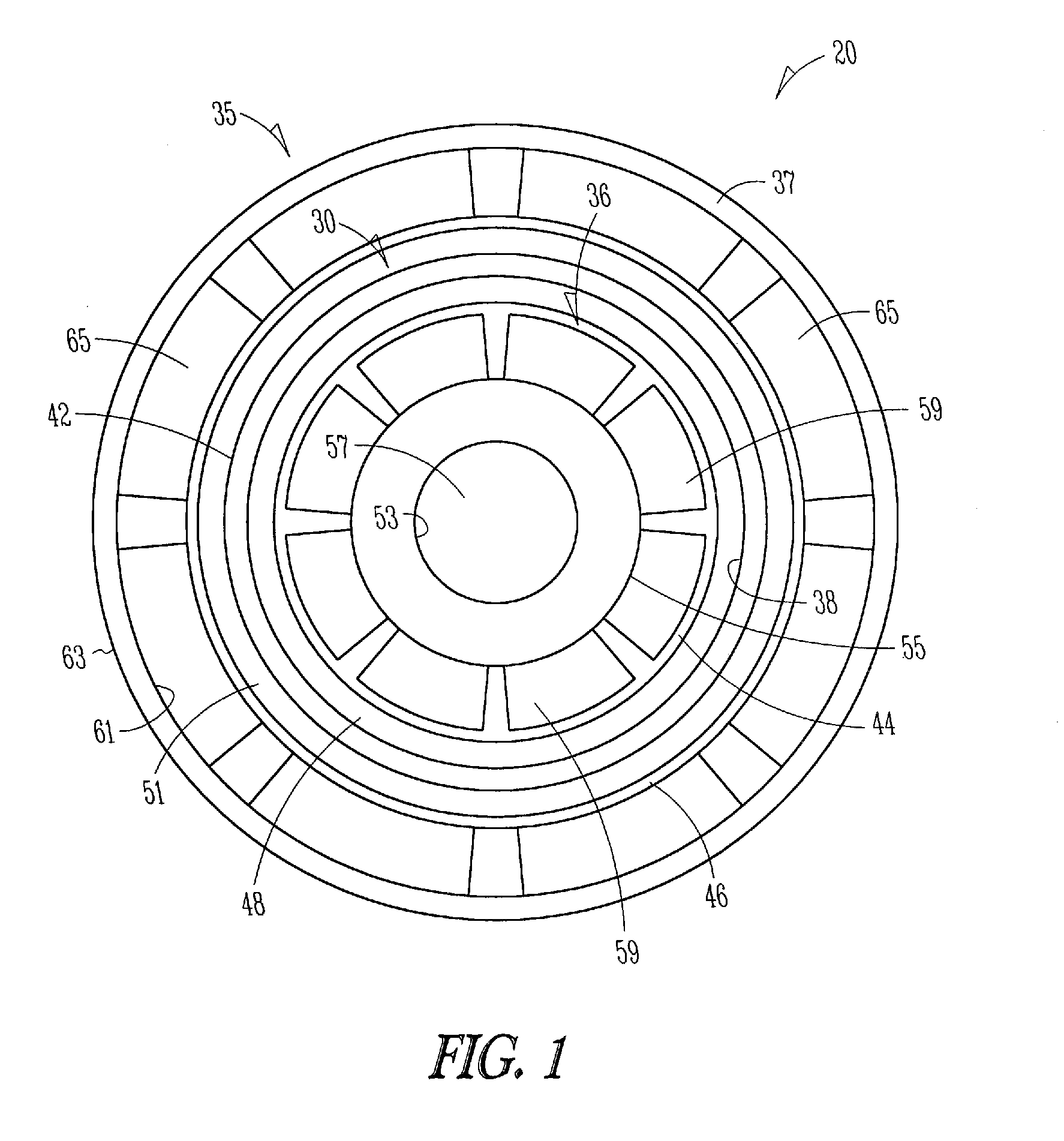
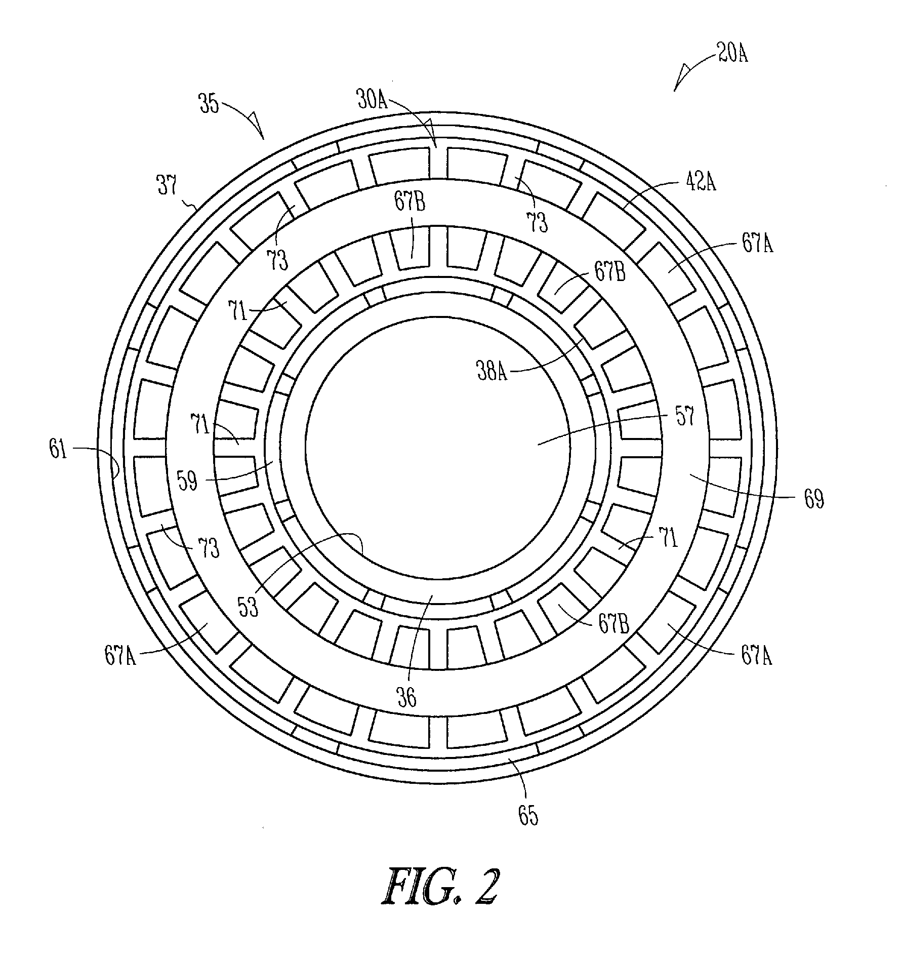
This document discusses, among other things, a stator with transposition between the windings or coils. The coils are free from transposition to increase the fill factor of the stator slots. The transposition at the end connections between an inner coil and an outer coil provide transposition to reduce circulating current loss. The increased fill factor reduces further current losses. Such a stator is used in a dual rotor, permanent magnet machine, for example, in a compressor pump, wind turbine gearbox, wind turbine rotor.

Description

STATEMENT REGARDING FEDERALLY SPONSORED RESEARCH OR DEVELOPMENT[0001]This invention was made with United States Government support awarded by the Department of Energy (DOE), Grant No. DE-AC36-99-GO10337. The United States Government has certain rights in this invention.BACKGROUND[0002]Dynamoelectric machines such as the large electrical generators include a rotor and a stator. The stator typically includes multiple phase windings, which are positioned in slots in a magnetic core. The movement of a rotor about an axis shifts a magnetic field that is associated with the rotor, thereby inducing a current to flow through each of the respective phase windings. However, the magnetic flux from the rotor and from the windings themselves may cause additional induced voltage and eddy currents in the windings. To combat this drawback, windings include multiple strands to minimize the eddy current loss. The flux in a generator is not uniform. Accordingly, the induced voltage varies from strand ...

Claims


Application Information

Patent Timeline
IPC IPC(8): H02K11/00H02K23/02H02K3/04H02K1/22H02K19/26H02K23/26H02K21/00H02K17/00
CPCH02K3/28Y02E10/725H02K21/12Y02E10/72
Inventor QU, RONGHAIJANSEN, PATRICK LEE
Owner GENERAL ELECTRIC CO
Why Eureka
Try Eureka