
Liquid crystal display device and fabricating method and driving method thereof

a technology of liquid crystal display and fabrication method, which is applied in the direction of static indicating devices, non-linear optics, instruments, etc., can solve the problems of increasing assembly costs of lcd panels, over-bright panels, and constant backlight 78, so as to improve the contrast ratio of liquid crystal display devices, reduce the fabrication cost of liquid crystal displays, and improve the uniformity of contrast of liquid crystal displays

Active Publication Date: 2007-12-27
LG DISPLAY CO LTD
View PDF8 Cites 31 Cited by
  • Summary
  • Abstract
  • Description
  • Claims
  • Application Information

AI Technical Summary

Benefits of technology

[0019]Accordingly, one advantage of the present invention is that it improves the contrast ratio of a liquid crystal display device under varying lighting conditions
[0020]Another advantage of the present invention is that it improves the uniformity of contrast of a liquid crystal display that is subject to uneven illumination by an external light source.
[0021]Still another advantage of the present invention is that it reduces the fabrication cost of a liquid crystal display that prevents a degradation of contrast under varying lighting conditions.
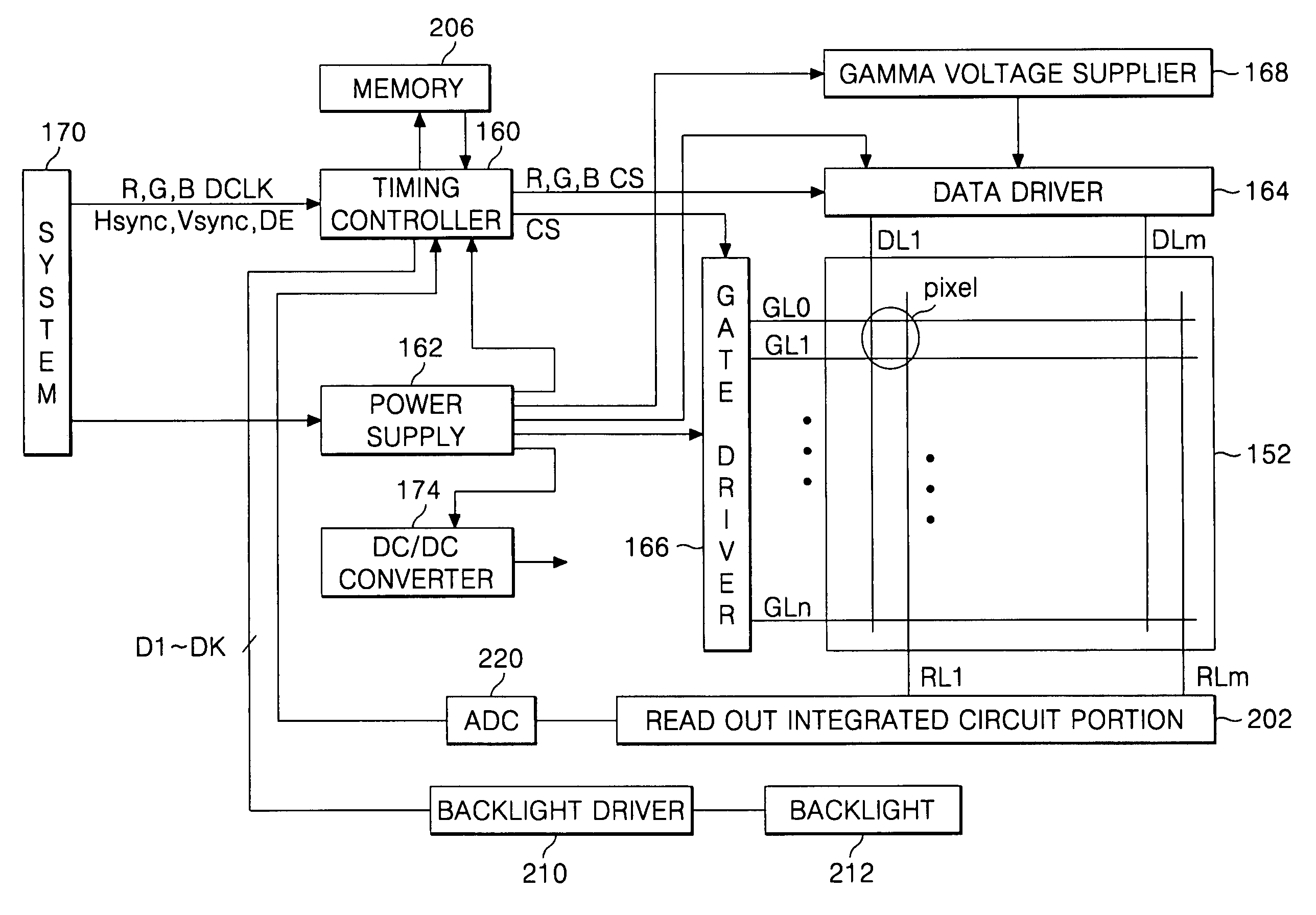
[0022]In order to achieve these and other objects of the invention, the present invention involves a liquid crystal display device having a TFT array substrate, which comprises a plurality of photo sensing devices formed on the TFT array substrate that sense an external light irradiated into the liquid crystal display panel; an integrated circuit portion that reads out signals corresponding to an illumination distribution by the external light in accordance with a sensing result by each of the photo sensing devices; a backlight having a plurality of light sources that independently supply light to the liquid crystal display panel in accordance with the illumination distribution; and a backlight driver that drives the backlight.
[0023]In another aspect of the present invention, the aforementioned and other advantages are achieved by a method of driving a liquid crystal display device, which comprises sensing an external light irradiated onto a liquid crystal display panel using a photo sensing device provided within the liquid crystal display device; measuring an illumination distribution corresponding to the external light in accordance with a result of the sensing by the photo sensing device; and adjusting a light amount supplied to the liquid crystal display panel in accordance with the illumination distribution.
[0024]In another aspect of the present invention, the aforementioned and other advantages are achieved by a method of fabricating a liquid crystal display device, which comprises forming a liquid crystal display panel that includes a plurality of photo sensing devices that sense an external light; preparing an integrated circuit portion that reads out a signal corresponding to illumination distribution, wherein the illumination distribution corresponds to a sensing result by the photo sensing devices; and preparing a plurality light sources that independently supply light to the liquid crystal display panel in accordance with the illumination distribution, wherein forming the liquid crystal display panel includes forming a thin film transistor array substrate including the photo sensing device, forming a color filter array substrate, and joining the thin film transistor array substrate with the color filter array substrate

Problems solved by technology

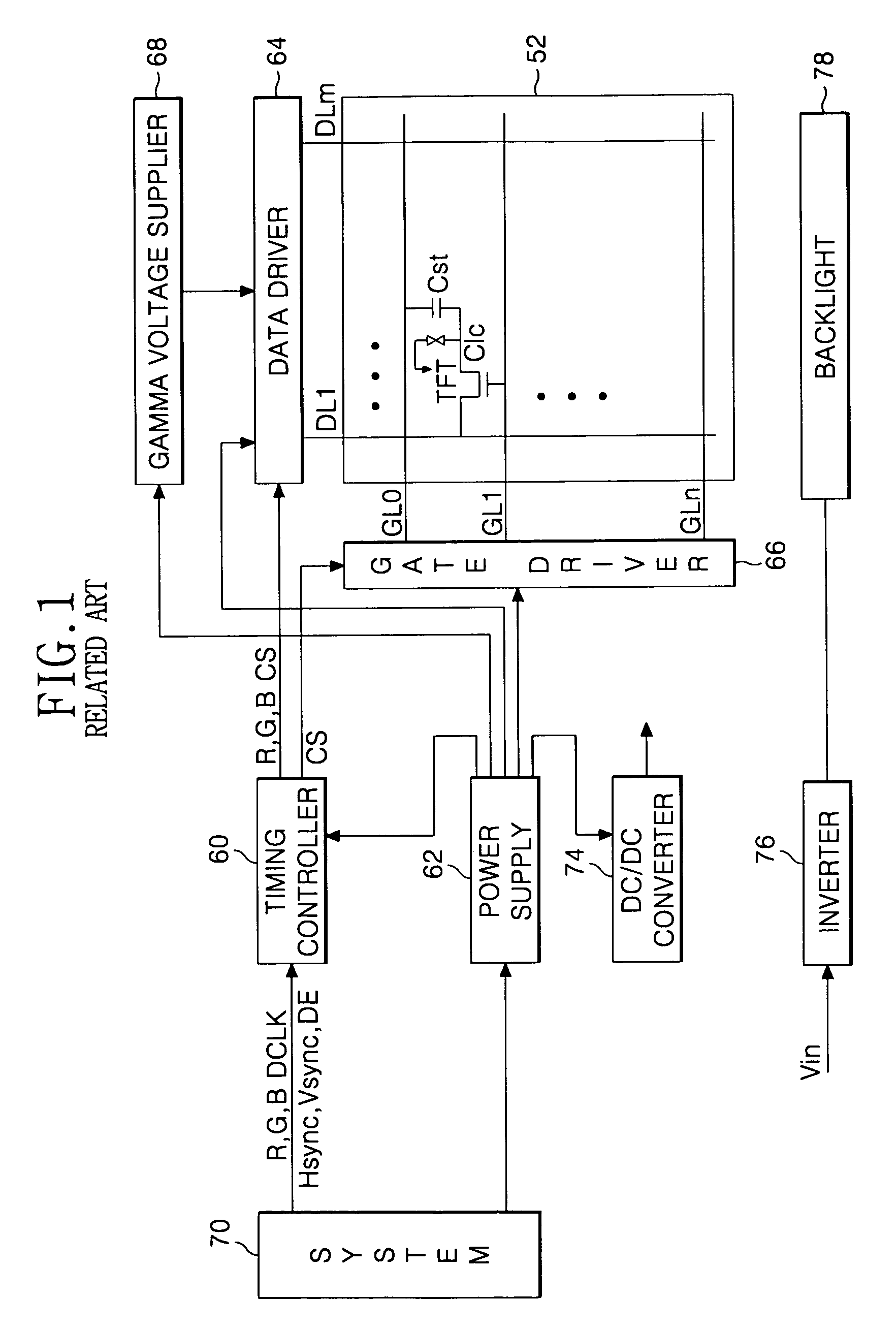
A problem associated with the related art is that light output from the backlight 78 is constant.
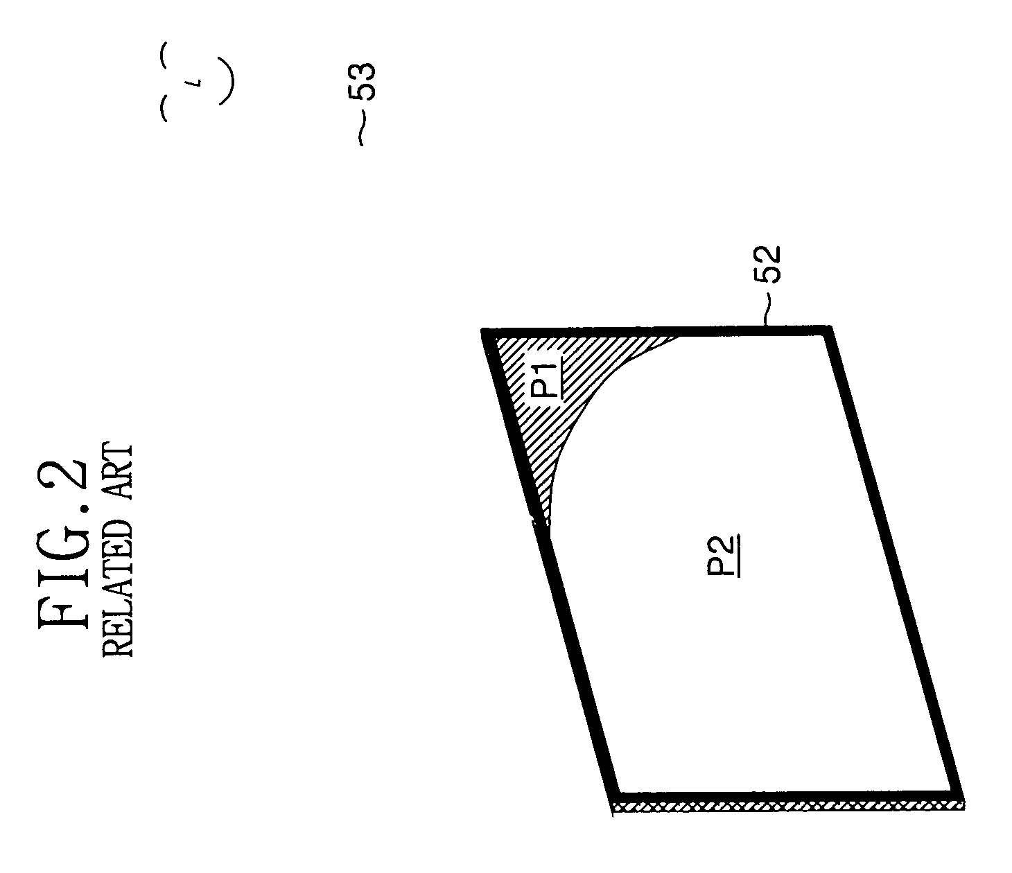
Conversely, if the ambient light is low, then the panel may be overly bright in comparison.
However, the addition of a separate photosensor increases assembly costs of the LCD panel.
Such related art solutions cannot selectively increase brightness of the backlight at a specific area of the liquid crystal display panel 52.

Method used


Image

  • Liquid crystal display device and fabricating method and driving method thereof
  • Liquid crystal display device and fabricating method and driving method thereof
  • Liquid crystal display device and fabricating method and driving method thereof

Examples


Embodiment Construction

[0041]FIG. 3 is a block diagram schematically illustrating an exemplary a liquid crystal display device according to an embodiment of the present invention. In a liquid crystal display device illustrated in FIG. 3, at least one photosensor is formed along with thin film patterns of the thin film transistor array substrate of the liquid crystal display panel 152. Accordingly, a separate external photodiode is not required. Here, the photosensor is directly formed within the liquid crystal display panel 152 to thereby improve accuracy of the sensor. Also, the amount of light produced by the backlight is selectively spatially increased only at an area of the liquid crystal display panel 152 that is illuminated by an external light source, as sensed by the photosensor, to thereby prevent a decrease in contrast for that illuminated area.

[0042]An exemplary configuration and an operation of the liquid crystal display device according to the present invention will be described with referenc...


PUM


Abstract

Disclosed is a liquid crystal display device, a fabricating method, and a driving method thereof that includes at least one integrated photosensor that senses external light illumination on the liquid crystal display device. A sensing signal from the at least one photosensors are converted into a digital signal that is stored to represent an external illumination distribution. The liquid crystal display device includes a backlight that has a plurality of light sources that may be independently driven. A controller generates a control signal that independently drives the light sources in a manner corresponding to the illumination distribution. In doing so, areas of the liquid crystal display device may be provided with a greater amount of light from a corresponding light source so that externally illuminated areas of the liquid crystal display device do not suffer from reduced contrast.

Description

[0001]This application claims the benefit of Korean Patent Application No. P2006-056744 filed in Korea on Jun. 23, 2006, which is hereby incorporated by reference.BACKGROUND OF THE INVENTION[0002]1. Field of the Invention[0003]This invention relates to a liquid crystal display device. More particularly, the invention relates to a liquid crystal display device, a fabricating method, and a driving method thereof that improve visibility and reduce power consumption as well as reduce fabricating costs.[0004]2. Description of the Related Art[0005]Generally, a liquid crystal display device LCD controls light transmittance of liquid crystal cells in accordance with video signals to display a picture. Such an LCD implementation typically includes an active matrix type LCD having a switching device for each cell. Such LCD display devices are used as computer monitors, office equipment, cellular phones and the like. The switching device for the active matrix LCD mainly employs an array of thi...

Claims


Application Information

Patent Timeline
IPC IPC(8): G09G3/36
CPCG02F1/13318G02F2001/13312G09G2360/144G09G2320/0633G09G3/3426G02F1/13312G09G3/36G02F1/133G02F1/136
Inventor KANG, HEE KWANGCHOO, KYO SEOP
Owner LG DISPLAY CO LTD
Learn More