
Laminated retardation optical element, process of producing the same, and liquid crystal display

a retardation optical element and retardation technology, applied in non-linear optics, instruments, optics, etc., can solve the problems of image quality and apt to be inferior, and achieve the effects of reducing contrast, reducing viewing angle dependency, and reducing contras

Inactive Publication Date: 2007-12-27
DAI NIPPON PRINTING CO LTD
View PDF2 Cites 12 Cited by
  • Summary
  • Abstract
  • Description
  • Claims
  • Application Information

AI Technical Summary

Benefits of technology

The present invention provides a laminated retardation optical element that can effectively compensate for the viewing angle dependency of the optical properties of a liquid crystal cell without degrading display performance. The element consists of an A plate-type retardation layer and a C plate-type retardation layer, which are optically bonded together. The A plate-type retardation layer acts as a brining layer with a phase difference of ¼ of the wavelength of light, while the C plate-type retardation layer acts as a negative C plate with a phase difference of ½ of the wavelength of light. The laminated retardation optical element can be produced using a specific process and is suitable for use in liquid crystal displays. It can also be patterned to improve its performance.

Problems solved by technology

For this reason, the above-described conventional liquid crystal display 100 has the problem (viewing angle dependency problem) that the image quality at the time when an image is viewed slantingly from a position not on the normal to the liquid crystal cell 104 is apt to be inferior to that at the time when the image is viewed from the front of the display.

Method used


Image

  • Laminated retardation optical element, process of producing the same, and liquid crystal display
  • Laminated retardation optical element, process of producing the same, and liquid crystal display
  • Laminated retardation optical element, process of producing the same, and liquid crystal display

Examples


example

[0203] A toluene solution (nematic liquid crystal solution) was prepared by dissolving a monomer containing, in its molecule, polymerizable acrylates at both ends and spacers between mesogen existing at the center and the acrylates, having a nematic-isotropic transition temperature of 110° C. (a monomer having a molecular structure represented by the above chemical formula (11)). To this nematic liquid crystal solution, a photopolymerization initiator (“Irgacure® 907” available from Ciba Specialty Chemicals K.K., Japan) was added in an amount of 5% by weight of the above-described monomer.

[0204] On the other hand, a transparent glass substrate was spin-coated with polyimide (“Optomer® AL1254” manufactured by JSR Corporation, Japan) dissolved in a solvent. After drying, a film of the polyimide (film thickness: 0.1 μm) was formed at 200° C., and was rubbed in one direction so that it could function as an alignment layer.

[0205] The glass substrate coated with the alignment layer was ...


PUM

PropertyMeasurementUnit
thicknessaaaaaaaaaa
angleaaaaaaaaaa
angleaaaaaaaaaa

Abstract

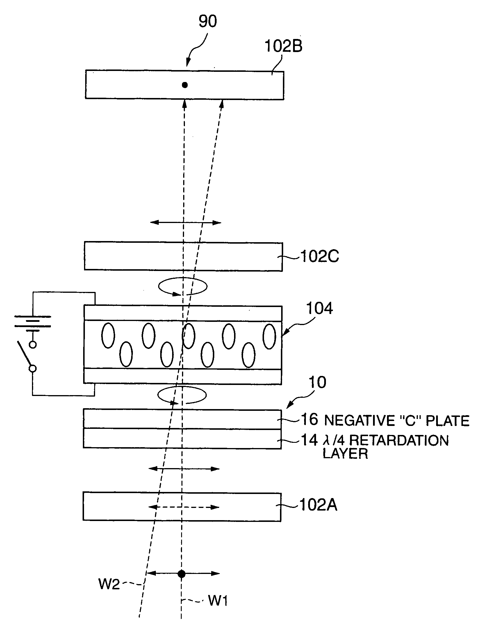
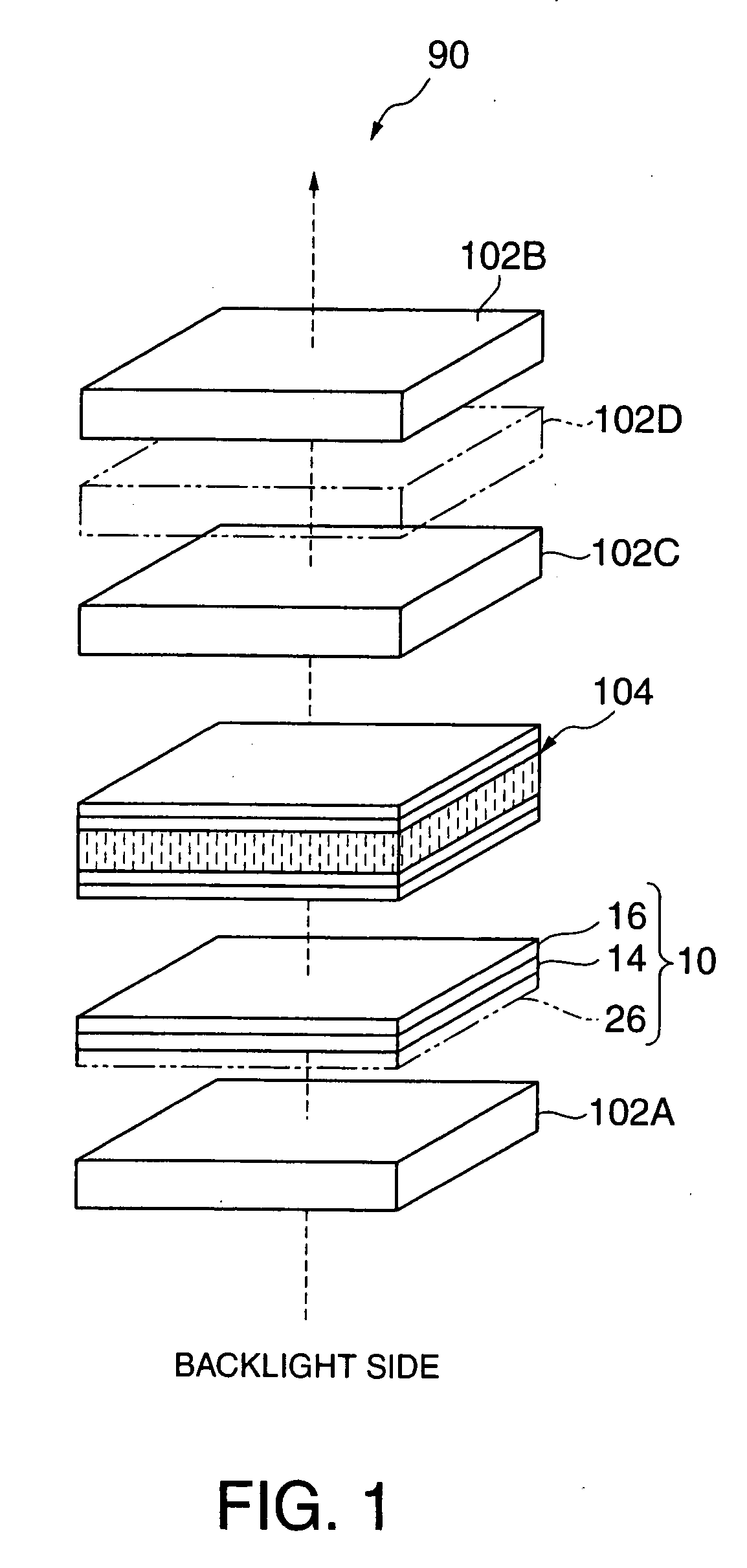
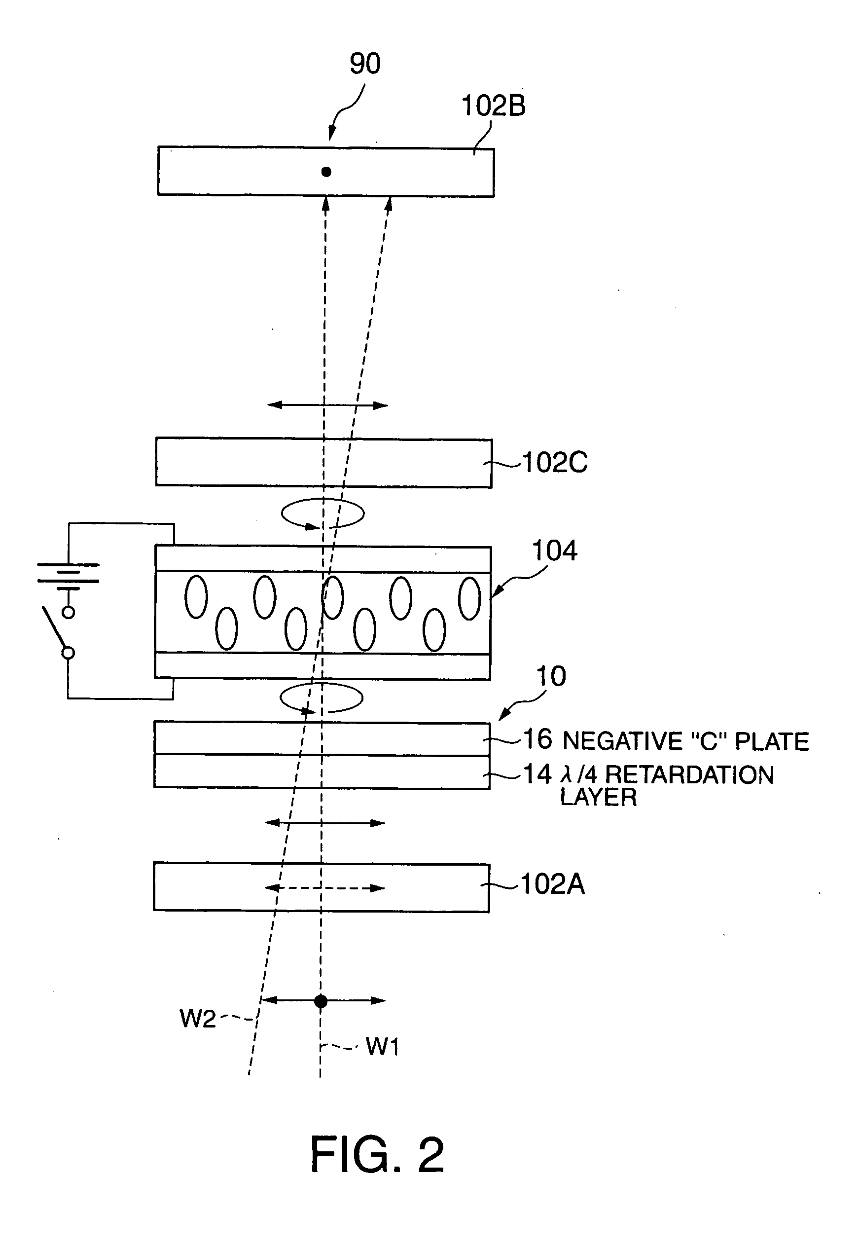
The present invention provides a laminated retardation optical element that never lowers contrast and thus never degrades display performance even when placed between a liquid crystal cell and a λ / 4 retardation film. In a liquid crystal display 90, a laminated retardation optical element 10 is placed between a polarizer 102A on the incident side and a liquid crystal cell 104, and a λ / 4 retardation film 102C is placed between a polarizer 102B on the emergent side and the liquid crystal cell 104. The laminated retardation optical element 10 comprises: a λ / 4 retardation layer 14 having the function of bringing, to light that passes through this retardation layer, a phase difference corresponding to a quarter of the wavelength of the light; and a C plate-type retardation layer 16 that acts as a negative C plate. The λ / 4 retardation layer 14 and the C plate-type retardation layer 16 are laminated to a transparent substrate 12 in the order mentioned, and are optically bonded to each other. The λ / 4 retardation layer 14 comprises as its main component a horizontally-aligned, cross-linked nematic liquid crystal, while the C plate-type retardation layer 16 comprises as its main component a cross-linked chiral nematic liquid crystal (a cross-linked nematic liquid crystal and a cross-linked chiral agent) or cross-linked discotic liquid crystal.

Description

[0001] This is a Continuation of application Ser. No. 10 / 655,582 filed Sep. 5, 2003. The entire disclosure of the prior application is hereby incorporated by reference herein in its entirety.BACKGROUND OF THE INVENTION [0002] 1. Field of the Invention [0003] The present invention relates to a laminated retardation optical element for use in a liquid crystal display or the like, especially a laminated retardation optical element having the function of effectively compensating for the viewing angle dependency of the optical properties of a liquid crystal cell (liquid crystal layer), being in the form of a thin film, and capable of effectively preventing lowering of contrast that is caused by interfacial reflection. The present invention also relates to a process of producing the same, and to a liquid crystal display comprising the laminated retardation optical element. [0004] 2. Description of Related Art [0005]FIG. 12 is an exploded, diagrammatic perspective view of a conventional, s...

Claims


Application Information

Patent Timeline
Patent Type & Authority Applications(United States)
IPC IPC(8): G02F1/1335G02F1/13363G02F1/139
CPCG02F1/1323G02F1/133634G02F1/1393G02F2413/14G02F2001/133638G02F2201/38G02F2413/09G02F2001/133567G02F1/133567G02F1/133631G02F1/133638
Inventor KASHIMA, KEIJI
Owner DAI NIPPON PRINTING CO LTD
Learn More