Aromatic vinyl ether based reverse-tone step and flash imprint lithography

a reverse-tone, lithography technology, applied in the field of step and flash imprint lithography, can solve the problems of inability to fully exclude molding or imprint material from template and substrate, range from extremely challenging to impossible, and complicate the process justly

Inactive Publication Date: 2007-12-27
GLOBALFOUNDRIES INC
View PDF3 Cites 50 Cited by
  • Summary
  • Abstract
  • Description
  • Claims
  • Application Information

AI Technical Summary

Benefits of technology

[0007]A first aspect of the present invention is a composition, comprising: one or more aromatic divinyl ethers; a photoacid generator; and a stabilizing / sensitizing agent.
[0008]A second aspect of the present invention is a method, comprising: forming on a substrate, a molding layer of a molding composition, the molding composition comprising one or more aromatic divinyl ethers; pressing a surface of a template into the molding layer, the template having a relief pattern on the surface, the molding layer filling voids in the relief pattern, the template not contacting the substrate; exposing the molding layer to actinic radiation, the actinic radiation converting the molding layer to a cured molding layer having thick and thin regions corresponding to the relief pattern; removing the template; filling the thin regions of the relief pattern with a backfill material; removing regions of the molding layer not protected by the backfill material to expose regions of the substrate; forming trenches in the exposed regions of the substrate; and removing any remaining molding layer and backfill material.
[0009]A third aspect of the present invention is a method, comprising: forming on a substrate, a transfer layer of a transfer composition; forming on the transfer layer, a molding layer of a molding composition, the molding composition comprising one or more aromatic divinyl ethers; pressing a surface of a template into the molding layer, the template having a relief pattern on the surface, the molding layer filling voids in the relief pattern, the template not contacting the transfer layer; exposing the molding layer to actinic radiation, the actinic radiation converting the molding layer to a cured molding layer having thick and thin regions corresponding to the relief pattern; removing the template; filling the thin regions of the relief pattern with a backfill material; removing regions of the molding layer and the transfer layer not protected by the backfill material to expose regions of the substrate; forming trenches in the exposed regions of the substrate; and removing any remaining molding layer, backfill material and transfer layer.

Problems solved by technology

Fabricating templates and producing imprints with such aspect ratios, however, can range from extremely challenging to impossible, especially as the imprinted features approach nanometer-scale dimensions.
Unfortunately, imprint lithography intrinsically possesses a characteristic that complicates the process just described.
When producing an imprint, the molding or imprint material cannot be fully excluded between the template and the substrate.
Removing the residual layer inevitably alters or damages the shape and / or the size of the imprinted features.
This problem worsens as the thickness or uniformity variations of the residual layer approaches or exceeds the height of the imprinted features.
In current practice, current SFIL-R formulations and processes are sensitive to the presence oxygen, have relatively low curing rates, high volatility, high viscosity, and low tensile strength, which can adversely affect the quality of the imprint mask.

Method used


Image

  • Aromatic vinyl ether based reverse-tone step and flash imprint lithography
  • Aromatic vinyl ether based reverse-tone step and flash imprint lithography
  • Aromatic vinyl ether based reverse-tone step and flash imprint lithography

Examples


first embodiment

[0064]Thus, the pattern of plateaus 145 of template 125 (see FIG. 1C) has been converted to a pattern of trenches 190 in substrate 100 (see FIG. 1I) in a negative imaging process in the present invention without the use of a residual layer removal or pre-burning step.

second embodiment

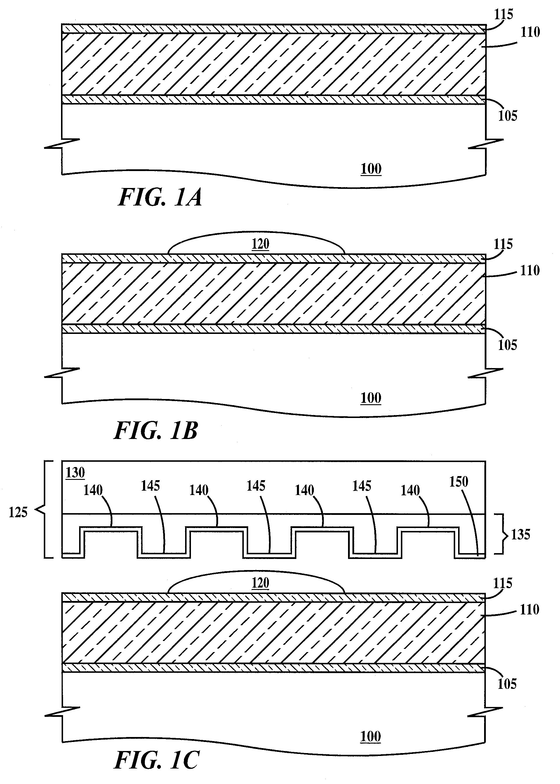
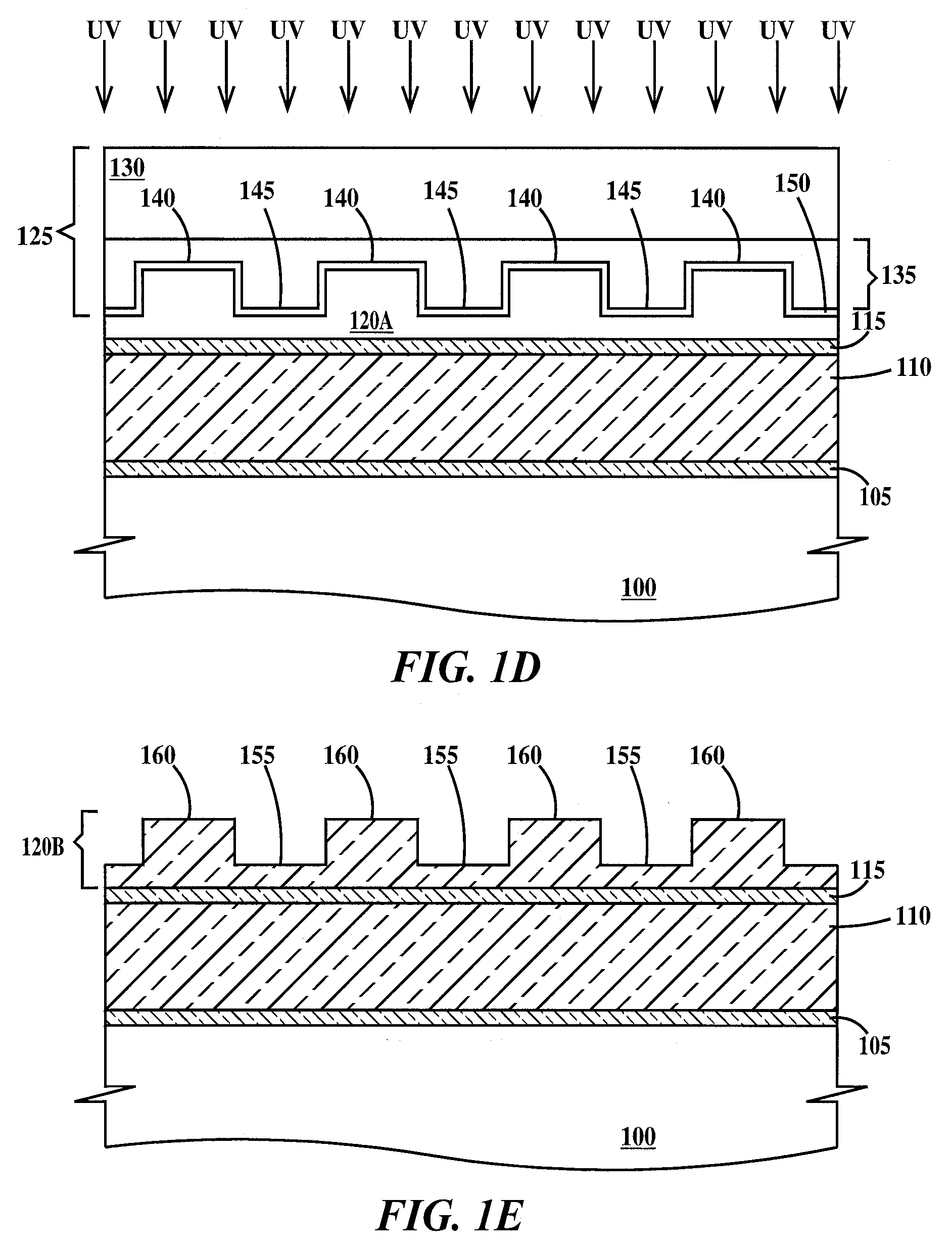
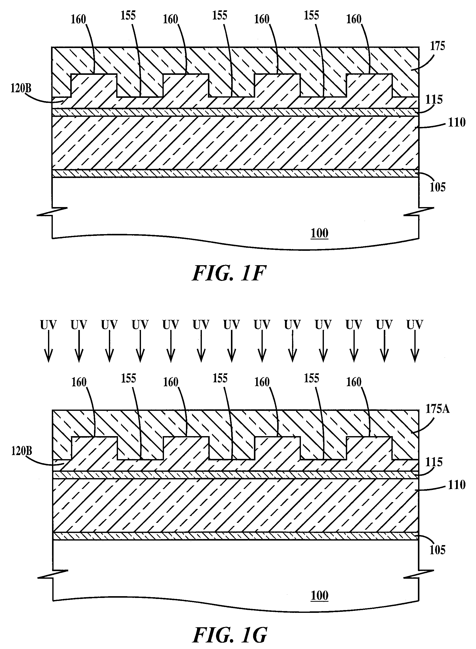
[0065]FIGS. 2A through 2K are cross-sectional drawings illustrating a SFIL process according to the present invention. In FIGS. 2A through 2J, adhesion layer 115 is optional and its composition has been described supra. FIG. 2A is similar to FIG. 1A, FIG. 2B is similar to FIG. 1B, and FIG. 2C is similar to FIG. 1C, except there is no transfer layer or second adhesion layer and puddle of molding composition 120 is formed on the top surface of adhesion layer 115 or the top surface of substrate 100 if no adhesion layer is used. An advantage of using aromatic vinyl ethers in the molding composition is that a single layer of material can serve as both the molding layer and the transfer layer, eliminating the need to apply a separate aromatic transfer layer.

[0066]FIGS. 2D, 2E, 2F, 2G and 2H are similar to FIGS. 1D, 1E, 1F, 1G and 1H respectively. In reference to FIG. 2E, the triethoxysilyl moiety of adhesion layer 115 (structure I) reacts with the —OH group on the surface of substrate 100...


PUM

PropertyMeasurementUnit
diameteraaaaaaaaaa
diameteraaaaaaaaaa
wavelengthaaaaaaaaaa

Abstract

A molding composition and a method of forming an pattern. The method includes forming on a substrate a molding layer of a molding composition of aromatic divinyl ethers; pressing the template into the molding layer, the template having a relief pattern, the molding layer filling voids in the relief pattern, the template not contacting the substrate; exposing the molding layer to actinic radiation, the actinic radiation converting the molding layer to a cured molding layer having thick and thin regions corresponding to the relief pattern; removing the template; filling the thin regions of the relief pattern with a backfill material; removing regions of the molding layer not protected by the backfill material to expose regions of the substrate; forming trenches in the exposed regions of the substrate; and removing any remaining molding layer and backfill material. A transfer layer may be used between the molding layer and the substrate.

Description

FIELD OF THE INVENTION[0001]This invention relates to processes for step and flash imprint lithography and materials for use in step and flash imprint lithography.BACKGROUND OF THE INVENTION[0002]Imprint lithography has emerged in various forms as a potential alternative to conventional photolithography because of its ability to print smaller features at low cost. Step and flash imprint lithography (SFIL) is a variant of imprint lithography that is amenable to the resolution and overlay requirements necessary for the fabrication of advanced semiconductor devices. In SFIL, a low-viscosity photosensitive molding material is molded between a mechanically rigid template having a relief pattern and a substrate and then is exposed to actinic radiation. The resulting hardened layer, having a three dimensional pattern, can be used as an etch mask to transfer the imprinted pattern into the substrate below.[0003]To form an effective etch mask with nanoscale features, it is often desirable to ...

Claims


Application Information

Patent Timeline
Patent Type & Authority Applications(United States)
IPC IPC(8): B05D3/12C08F2/46
CPCB82Y10/00B82Y40/00C08F2/50G03F7/038G03F7/0002G03F7/0045C08F216/125
Inventor DIPIETRO, RICHARD ANTHONYHART, MARK WHITNEYHOULE, FRANCES ANNEITO, HIROSHI
Owner GLOBALFOUNDRIES INC
Why Eureka
Try Eureka